2
• LED indicators for easy viewing
• Each USB output port contains 500 mA of power
6. OPERATION CONTROLS AND FUNCTIONS
TRANSMITTER
6.1 Front Panel
1 2
3
4
5
6
7
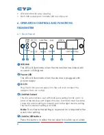
1
USB Link
This LED will illuminate when the transmitter has linked with
receiver’s USB signal.
2
Power LED
This LED will illuminate when the device is plugged with
power supply.
3
DC 5V
Plug the 5V DC power supply into the unit and connect the
adaptor to an AC outlet.
4
Link Pair Select
This dip switch allows user with multi-pairs setting for link up to 16
pairs of the devices with single IP router. Each pair must have the
same dip switch setting in order to pair to the right device setting.
The factory default setting is at 0000.
Note:
To activate the setting a re-power on is required after
each new setting.
5
Link On/Off button
Press this button to allow the receiver to be link up or unlink

