


47
HSTP3T 60-500 KE User Manual
Chapter 3 LCD Panel
breaker open”, “Byp Sequence Err” and “Ip Neutral Lost”. If there
is any relevant alarm, first clear this alarm.
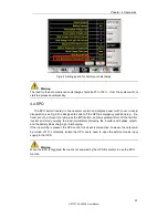
1. Then check and confirm if the bypass frequency displayed on
the LCD are within the setting range. Note that the rated
frequency are respectively specified by “Output Frequency”.
2. If the displayed voltage is abnormal, measure the actual
bypass frequency. If the measurement is abnormal, check the
external bypass power supply. If the alarm occurs frequently, use
the configuration software to increase the bypass high limit set
point according to the user’s suggestions
23
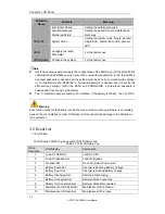
Exceed Tx Times
Lmt
The load is on bypass because the output overload transfer and
re-transfer is fixed to the set times during the current hour. The
system can recover automatically and will transfer back to the
inverter with 1 hour
24
Output Short
Circuit
Output shorted Circuit.
Fist check and confirm if loads have something wrong.
Then check and confirm if there is something wrong with
terminals, sockets or some other power distribution unit.
If the fault is solved, press “Fault Clear” to restart UPS.
25
Battery EOD
Inverter turned off due to low battery voltage. Check the mains
power failure status and recover the mains power in time
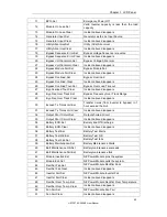
26
Battery Test
System transfer to battery mode for 20 seconds to check if
batteries are normal
27
Battery Test OK
Battery Test OK
28
Battery
Maintenance
System transfer to battery mode until to be 1.1*EOD voltage to
maintenance battery string
29
Battery
Maintenance OK
Battery maintenance succeed
30
Module inserted
Power Module is inserted in system.
31
Module Exit
Power Module is pulled out from system.
32
Rectifier Fail
The N# Power Module Rectifier Fail, The rectifier is fault and
results in rectifier shutdown and battery discharging.
33
Inverter Fail
The N# Power Module Inverter Fail. The inverter output voltage is
abnormal and the load transfers to bypass.
34
Rectifier Over
Temp.
The N# Power Module Rectifier Over Temperature. The
temperature of the rectifier IGBTs is too high to keep rectifier
running. This alarm is triggered by the signal from the
temperature monitoring device mounted in the rectifier IGBTs.
The UPS recovers automatically after the over temperature
signal disappears.
If over temperature exists, check:
1. Whether the ambient temperature is too high.
2. Whether the ventilation channel is blocked.
3. Whether fan fault happens.
4. Whether the input voltage is too low.
35
Fan Fail
At least one fan fails in the N# power module.
36
Output Over load The N# Power Module Output Over Load. This alarm appears
when the load rises above 100% of nominal rating. The alarm
automatically resets once the overload condition is removed.
1. Check which phase has overload through the load (%)
displayed in LCD so as to confirm if this alarm is true.


