


21
HSTP3T 60-500 KE User Manual
Chapter 2 Installation Instruction
2.6.3 Circuit Breaker
The circuit breakers (CB) for the system are recommended in Table 2.4.
Table 2.4 Recommended CB
Installed position
60kVA
80kVA
90kVA
100kVA
120kVA
150kVA
Main input CB
125A/3P
160A/3P
160A/3P
250A/3P
250A/3P
320A/3P
Bypass input CB
125A/3P
160A/3P
160A/3P
250A/3P
250A/3P
320A/3P
Output CB
125A/3P
160A/3P
160A/3P
250A/3P
250A/3P
320A/3P
Manual Bypass CB
125A/3P
160A/3P
160A/3P
250A/3P
250A/3P
320A/3P
Battery CB
160A,
250Vdc
225A,
250Vdc
225A,
250Vdc
250A,
250Vdc
400A,
250Vdc
400A,
250Vdc
Installed position
200kVA
250kVA
300kVA
400kVA
500kVA
Main input CB
400A/3P
630A/3P
630A/3P
800A/3P
800A/3P
Bypass input CB
400A/3P
630A/3P
630A/3P
800A/3P
800A/3P
Output CB
400A/3P
630A/3P
630A/3P
800A/3P
800A/3P
Manual Bypass CB
400A/3P
630A/3P
630A/3P
800A/3P
800A/3P
Battery CB
630A,
250Vdc
800A/3P
250Vdc
1000A/3P
250Vdc
1000A,
250Vdc
1250A,
250Vdc
Attention
The CB with RCD (Residual Current Device) is not suggested for the system.
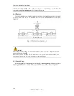
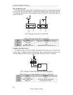
2.6.4 Connecting Power Cables
The steps of connecting power cables are as follows:
1. Verify that all the switches of the UPS are completely open and the UPS internal
maintenance bypass switch is opened. Attach necessary warning signs to these
switches to prevent unauthorized operation.
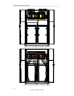
2. Open the back door of the cabinet, remove the plastic cover. The input and output
terminal, battery terminal and protective earth terminal are shown in Fig.2-12.
Fig.2-12-1 Connections terminals of 60kVA, 90kVA and 120kVA


