background image

APPENDIX 

CyberMed M156S User’s Manual 

37

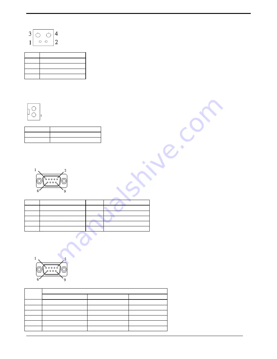
J44 – Reset Button 


Pin # 

Signal Description 

1 SYS_RESET# 
2 GND 
3 GND 
4 GND 


J45 – Reset connector 


Pin # 

Signal Description 

1 SYS_RESET# 
2 GND 


J46 – External COM2 Connector 


Pin # 

Signal Description 

Pin # 

Signal Description 

1 232_DCD 

2  232_SIN

3 232_SOUT 

4  232_DTR

5 GND 

6  232_DSR 

7 232_RTS 

8  232_CTS 

9 232_RI 

10 Not 

Used 


J47 – External COM1 Connector 


Pin # 

Signal Description 

RS-232 RS-422 

RS-485 

Carrier Detect 

Transmit Data - 

Transmit Data - 

Receive Data 

Transmit Data + 

Transmit Data + 

Transmit Data 

Receive Data + 

NC 

Data Terminal Ready 

Receive Data - 

NC 

5 Ground 

NC 

NC 

Data Set Ready 

NC 

NC 

Содержание CyberMed M156S

Страница 1: ...edical Panel PC User s Manual Copyright 2016 All rights reserved All other brand names are registered trademarks of their respective owners The information contained in this document is subject to change without notice ...

Страница 2: ...CyberMed M156S User s Manual ii Version Change History Date Version Description Remark 11 08 2016 1 0 First release Steven Huang ...

Страница 3: ...rk of Realtek Semi Conductor Co Ltd C T is a trademark of Chips and Technologies Inc UMC is a trademark of United Microelectronics Corporation ITE is a trademark of Integrated Technology Express Inc Intel is a trademark or registered trademark of Intel Corporation Microsoft Windows is a registered trademark of Microsoft Corporation Winbond is a registered trademark of Winbond Electronics Corporati...

Страница 4: ...s equipment is believed to be causing harmful interference to radio or television reception this can be determined by turning the equipment on and off If interference is occurring the user is encouraged to try to correct the interference by one or more of the following measures Increase the separation between the equipment and the receiver Connect the equipment to a power outlet on a circuit diffe...

Страница 5: ...commended In addition when installing the unit by suspending it also requires two or more people 4 Before suspending the unit make sure the material used for suspension is sturdy and stable If not properly suspended the display unit may fall and cause serious injury to people standing nearby as well as to the unit itself 5 If you wish to mount the display unit remember to use only the mounting har...

Страница 6: ...ources 7 Do not place the unit in a location where it will come in contact with fumes or steam 8 Remember to keep the medical panel PC unit away from the presence of dust 9 If water has flow in or seep in immediately disconnect the open frame unit Then contact a service technician for repairs Ventilation Spacing 1 Do not cover or block the openings on the top and back sides of the display unit Ina...

Страница 7: ...unit Error message Troubleshooting No power 1 Connect the AC adapter to the computer and then plug it into an AC outlet 2 Turn on the computer Servicing Repairing Maintenance Safety Checks 1 If the unit is not functioning properly observe the performance level of the display closely to determine what type of servicing is needed 2 Do not attempt to repair the medical panel PC unit on your own Disas...

Страница 8: ...ements for safety EN 60601 1 1 IEC 60601 1 1 Medical electrical equipment Part 1 1 General requirements for safety Collateral standard Safety requirements for Medical electrical systems EN 60601 1 2 IEC 60601 1 2 Medical electrical equipment Part 1 2 General requirements for safety Collateral standard Electromagnetic compatibility Requirements and tests Accessory equipment connected to the analog ...

Страница 9: ...se of used batteries according to the instructions The sound pressure level at the operator s position according to IEC 704 1 1982 is no more than 70dB A A Grounding reliability can only be achieved when the equipment is connected to an equivalent receptacle marked Hospital Only or Hospital Grade B Use a power cord that matches the voltage of the power outlet which has been approved and complies w...

Страница 10: ...s declaration electromagnetic emissions 6 Guidance and manufacturer s declaration electromagnetic immunity 6 Immunity 7 Cleaning Disinfecting 9 Getting Started 10 System Set Up 10 Dimension 11 System View 12 Disconnect Device 14 BIOS Setup 15 Appendix 23 A Jumper settings and Connectors 23 B Battery Pack Specifications optional kit 39 C How to disable battery when system hang up 39 D Cybernet e re...

Страница 11: ...M156S includes all the features of a powerful computer into a slim and attractive chassis with a 15 6 wide screen 400nits TFT display with 1366 x 768 resolutions Integrating with high brightness LCD is easier to analyze DICOM image The Cybermed M156S is compact Giga LAN and selectable WLAN network compatible PC with full safety and medical approval and features to control a dedicated system with a...

Страница 12: ...al Station please make sure that the following items have been shipped The CyberMed M156S Medical Panel PC unit User s manual chipset drivers Power Adapter x 1 Mf Sinpro type model HPU101 105 Power cord Hospital grade used US type or other type in UK EU etc Screw x 8 VESA 75 100 use ...

Страница 13: ...reen Easy wipe surfaces with no internal corners Fanless solution Two mini PCI e expansion One full size and one half size HDD Anti vibration mechanism Supports PCI E x4 riser card option Easy clean full flat 5 wire resistive touch screen customized order configuration USB LAN COM isolated module by different configuration optional order configuration Optional WLAN Bluetooth module with inner ante...

Страница 14: ...on Optional Isolated 4KV USB2 0 1 Isolated 4KV GigaLAN 1 Isolated 4KV RS 232 1 RS 232 422 485 1 The isolated ports verified through Dielectric test 4000Vac only RS 232 port 1 RS 232 422 485 port 1 USB 3 0 port 2 USB 2 0 port 2 DC in w lock function 1 Gigabit LAN RJ 45 Connectors 2 DP output 2 Sound Line in 1 Line out 1 2W Speaker 2 LCD Specifications Display Type 15 6 wide LED backlight Max Resolu...

Страница 15: ...0 C 4 F 140 F Humidity Operating 10 to 90 40 C non condensing Storage Transportation 10 to 90 non condensing Vibration Operating 15g 0 53 oz 11 ms half sine wave Non operating 50g 1 76 oz 11 ms half sine wave Shock Operating 5 17 Hz Amplitude 0 117 500Hz Acceleration 1 0G Non operating 10 55Hz 0 15g 55 500Hz 2 0g Altitudes Operational up to 3000 m 9842 feet Shipping up to 12192 m 40000 feet Pressu...

Страница 16: ...mmunications equipment Rated maximum output power of transmitter W Separation distance according to frequency of transmitter m 150 kHz to 80 MHz d 1 2 80 MHz to 800 MHz d 1 2 800 MHz to 2 5 GHz d 2 3 0 01 0 12 0 12 0 23 0 1 0 38 0 38 0 73 1 1 2 1 2 2 3 10 3 8 3 8 7 3 100 12 12 23 For transmitters rated at a maximum output power not listed above the recommended separation distanced in meters m can ...

Страница 17: ...acteristic of a typical location in a typical commercial or hospital environment NOTE UT is the a c mains voltage prior to application of the test level Guidance and manufacturer s declaration electromagnetic immunity The model CyberMed M156S is intended for use in the electromagnetic environment specified below The customer or the user of the model CyberMed M156S should assure that it is used in ...

Страница 18: ...adio cellular cordless telephones and land mobile radios amateur radio AM and FM radio broadcast and TV broadcast cannot be predicted theoretically with accuracy To assess the electromagnetic environment due to fixed RF transmitters an electromagnetic site survey should be considered If the measured field strength in the location in which the model CyberMed M156S is used exceeds the applicable RF ...

Страница 19: ...ll liquid on the device disconnect the unit from the power source Contact your Biomed regarding the continued safety of the unit before placing it back in operation Do not spray cleaning agent on the chassis Do not use disinfectants that contain phenol Do not autoclave or clean the CyberMed M156S or its peripherals with strong aromatic chlorinated ketone ether or Esther solvents sharp tools or abr...

Страница 20: ...ystem and the plug to an electrical outlet 4 Waiting for 3 seconds then press the power switch on the front panel of the system once to turn on the system power 5 If necessary run the BIOS SETUP programs to configure the system Caution In order to boot up system from USB CD DVD drive please connect USB CD DVD drive turn on computer power keep on pressing F11 key go into BIOS quick boot menu select...

Страница 21: ...CyberMed M156S User s Manual 11 Dimension CyberMed M156S VESA Mount Screw type M4 ...

Страница 22: ...Battery mode Amber Battery low Amber blinking 2 Power with LED status indicator ON Green OFF dark 3 Volume adjustment 4 Volume adjustment 5 Brightness 6 Brightness 7 LCD on off with LED status indicator LCD ON dark LCD OFF Amber 8 Clean me with LED status indicator ON Amber OFF dark a Keep on contacting 5 seconds to active b keep contacting 5 seconds to release c auto release after 60 seconds Webc...

Страница 23: ...CyberMed M156S User s Manual 13 I O parts Isolated I O parts ...

Страница 24: ...Disconnect Device Turn off the system Turning off CyberMed M156S properly is important for system reliability 1 On the start menu click Shut down and select OK Unplug the power cord from the power adapter jack to disconnect the device ...

Страница 25: ...OS is immediately activated Pressing the Del key immediately allows you to enter the Setup utility If you are a little bit late pressing the Del key POST Power On Self Test will continue with its test routines thus preventing you from invoking the Setup If you still wish to enter Setup restart the system by pressing the Reset button or simultaneously pressing the Ctrl Alt and Delete keys You can a...

Страница 26: ...t the system time Use the Tab key to switch between time elements Advanced Trusted Computing Configuration Enables or disables BIOS support for security device O S will not show Security Device TCG EFI protocol and INT1A interface will not be available ACPI Settings Enable Hibernation Enables or Disables System ability to Hibernate 0S S4 Sleep State This option may be not effective with some OS AC...

Страница 27: ...ttings Select an optimal settings for super IO Device Serial Port 4 Configuration Serial Port Enable or Disable Serial Port COM Serial Port 5 Configuration Serial Port Enable or Disable Serial Port COM Serial Port 6 Configuration Serial Port Enable or Disable Serial Port COM Change Settings Select an optimal settings for super IO Device Intel R Smart Connect Technology ISCT Support Enable Disable ...

Страница 28: ...old time Locked Status Hold Time Number of minutes to keep lock status 0 means lock always 1 100 minutes mean lock hold time Power key Enable Disable power key Mute key Enable Disable Mute key Volume Up Dn keys Enable Disable Vol Vol key LCD Brightness Up Dn keys Enable Disable LCD Brightness up down key LCD Backlight On Off key Enable Disable LCD Backlight key Lock key Enable Disable Lock key Web...

Страница 29: ...ble only for EFI applications XHCI Hand off Enable Disable XHCI Controller Legacy support USB Mass Storage Driver Support Enable Disable USB Mass Storage Driver Support Chipset North Bridge Config Intel IGD Settings South Bridge High Precision Timer Enable or Disable the High Precision Event Timer Audio Controller Control Detection of the Azalia device Disabled Azalia will be unconditionally disab...

Страница 30: ...ser Password P0 TOSHIBA MQ01 HDD Security Configuration for selected drive Boot Setup Prompt Timeout Number of seconds to wait for setup activation key 65535 0xFFFF means indefinite waiting Bootup Numlock State Selects the keyboard NumLock state PXE Boot PXE Network Boot Enable Disable OS Selection OS Selection ...

Страница 31: ...es and Reset Reset system setup without saving the changes Save Changes Save the changes done so far to any of setup options Discard Changes Discard the changes done so far to any of setup options Restore Defaults Restore load default values for all the setup options Save as User Defaults Save the changes done so far as User Defaults Restore User Defaults Restore the User Defaults to all the setup...

Страница 32: ...CyberMed M156S User s Manual 22 Reset System with ME disable ModeMEUD000 ME will runs into the temporary disable mode Ignore if ME Ignition FWMEUD001 ...

Страница 33: ...aders and connectors All of the configuration jumpers on M156S are in the proper position Note Some of jumpers or connectors will be removed base on system configuration Jumper and Connector Definition Block JP1 Touch Panel Type Selection Description Jumper Setting 3M type 1 2 3 4 default ELO type 5 6 7 8 JP2 LVDS Power Selection Description Jumper Setting ...

Страница 34: ...4 3 3VS for 10 12 15 5 6 7 8 5VS for 17 19 1 2 3 4 default JP3 Backlight Type Selection Description Jumper Setting Analog Inverter 1 2 PWM Inverter 2 3 JP4 Backlight control level Selection Description Jumper Setting 3 3V 1 2 5V OPEN default ...

Страница 35: ...t 8 wire 1 2 JP3 Touch Panel Type Selection Description Jumper Setting 3M type 1 2 3 4 default ELO type 5 6 7 8 JP4 LVDS Power Selection Description Jumper Setting 5VS for 17 19 21 5 1 2 3 4 default 3 3VS for 10 12 15 5 6 7 8 JP5 Panel Type Selection 0 1 GPIO3 JP5 1 2 short JP5 1 2 open GPIO2 JP5 3 4 short JP5 3 4 open GPIO1 JP5 5 6 short JP5 5 6 open GPIO0 JP5 7 8 short JP5 7 8 open JP6 CMOS Clea...

Страница 36: ... User s Manual 26 CMOS Clear 2 3 JP8 JP9 Support Y cable with DVI VGA Description Jumper Setting Description JP8 DVI Open DVI DVI VGA Short DVI VGA JP10 COM4 Power Selection Description Jumper Setting 5VS 2 3 default 12VS 1 2 ...

Страница 37: ...Ground 3 Ground 4 5VS PJ4 Power Jack Connector Pin Signal Description 1 DC In 2 DC In 3 Ground 4 Ground 5 Ground J1 LCD Inverter Interface Pin1 Pin Signal Description 1 12VS 2 12VS 3 Backlight Adjust 4 Backlight Enable 5 Ground 6 Ground J2 Internal Webcam USB 2 0 Pin Header Pin1 Pin Signal Description 1 5VSB 2 5VSB 3 Data ...

Страница 38: ...M6 35 DQ11 103 CK0 171 DQS6 36 DQ15 104 CK1 172 VSS 37 VSS 105 VDD 173 VSS 38 VSS 106 VDD 174 DQ54 39 DQ16 107 A10 175 DQ50 40 DQ20 108 BA1 176 DQ55 41 DQ17 109 BA0 177 DQ51 42 DQ21 110 RAS 178 VSS 43 VSS 111 VDD 179 VSS 44 VSS 112 VDD 180 DQ60 45 DQS2 113 WE 181 DQ56 46 DM2 114 S0 182 DQ61 47 DQS2 115 CAS 183 DQ57 48 VSS 116 ODT0 184 VSS 49 VSS 117 VDD 185 VSS 50 DQ22 118 VDD 186 DQS7 51 DQ18 119...

Страница 39: ...4 B_RxIn3 35 A_RxIn3 36 B_RxIn3 37 Ground 38 Ground 39 Ground 40 Ground J5 Res Touch Panel Interface Pin Signal Description 8 wire 4 wire 5 wire 1 UL X UL X UL X 2 UR Y UR Y UR Y 3 N A N A PROBE 4 LR X LR X LR X 5 LL Y LL Y LL Y 6 X _DRIVE N A N A 7 Y _DRIVE N A N A 8 X _DRIVE N A N A 9 Y _DRIVE N A N A J6 J12 Mini PCI Express Socket ...

Страница 40: ...VSB 3 Reserved 4 GND 5 Reserved 6 1 5VS 7 CLKREQ 8 Reserved 9 GND 10 Reserved 11 REFCLK 12 Reserved 13 REFCLK 14 Reserved 15 GND 16 Reserved 17 Reserved 18 GND 19 Reserved 20 Reserved 21 GND 22 PERST 23 PERn0 24 3 3VSB 25 PERp0 26 GND 27 GND 28 1 5VS 29 GND 30 SMB_CLK 31 PETn0 32 SMB_DATA 33 PETp0 34 GND 35 GND 36 USB_D 37 GND 38 USB_D 39 3 3VSB 40 GND 41 3 3VSB 42 Reserved 43 GND 44 Reserved 45 C...

Страница 41: ...HDD LED Pin Signal Description 1 SATA_LED 2 3 3VSB 3 3 3VSB 4 PWR_LED J17 For JTAG Pin Signal Description Pin Signal Description 1 TRST 2 3 3VSB 3 TMS 4 RDY 5 TDI 6 GND 7 TCK 8 GND 9 TDO 10 GND J18 TPM ID 394 Pin Signal Description Pin Signal Description 1 LPC AD0 2 PLT reset 3 LPC AD1 4 SERIRQ 5 LPC AD2 6 3 3VS 7 LPC AD3 8 5VSB 9 LPC Frame 10 CLKRUN 11 Debug CLK 12 SMB CLK ...

Страница 42: ...5 SUS_STAT 16 3 3VSB J19 J21 Standard SATA Interface Pin Signal Description 1 Ground 2 Tx 3 Tx 4 Ground 5 Rx 6 Rx 7 Ground J23 PS2 KB MS Pin Signal Description 1 KBDATA 2 MSDATA 3 Ground 4 5VSB 5 KBCLK 6 MSCLK J24 EC Reset Pin Signal Description 1 EC_RESET 2 GND ...

Страница 43: ...nal Description Pin Signal Description 1 GEN_GPO1 2 GEN_GPI1 3 GEN_GPO2 4 GEN_GPI2 5 GEN_GPO3 6 GEN_GPI3 7 GEN_GPO4 8 GEN_GPI4 9 5V 10 5V 11 GND 12 GND J28 CAP Front Bezel Button Light Sensor Connect Pin Signal Description 1 5VSB 2 3 3VSB 3 KP_SCL 4 KP_SDA 5 PWR_LED 6 KP_P_LED 7 SATA_LED 8 GND 9 GND J29 Light Sensor Connect ...

Страница 44: ...COM4 Serial Port Pin Signal Description Pin Signal Description 1 232_DCD 2 232_DSR 3 232_SIN 4 232_RTS 5 232_SOUT 6 232_CTS 7 232_DTR 8 232_RI 9 GND 10 5VS 12VS J31 Internal COM4 TTL Pin Signal Description Pin Signal Description 1 DCD 2 DSR 3 SIN 4 RTS 5 SOUT 6 CTS 7 DTR 8 RI 9 GND 10 5VS J32 External USB 3 0 Port Pin Signal Description 1 5V 2 Data 3 Data ...

Страница 45: ...H for Speaker Pin Signal Description J33 RIGHT CH J42 LEFT CH 1 ROUT LOUT 2 ROUT LOUT J34 External RJ45 Ethernet Port Pin Signal Description 1 Data0 2 Data0 3 Data1 4 Data2 5 Data2 6 Data1 7 Data3 8 Data3 J35 Power Switch connect Pin Signal Description 1 Power ON 2 GND J36 J37 J38 External USB 2 0 Port ...

Страница 46: ...ND 12 NC 13 NC 14 5V 15 GND 16 Hot Plug Detect 17 DVI Data0 18 DVI Data0 19 GND 20 CRT_CLK 21 CRT_DATA 22 GND 23 DVI Clock 24 DVI Clock C1 CRT_R C2 CRT_G C3 CRT_B C4 HSYNC C5 GND C6 GND J40 J41 External Audio Phone Jack Pin Signal Description J40 Line Out stereo Green J41 Microphone stereo Pink J43 Internal COM3 Serial Port Pin Signal Description Pin Signal Description 1 232_DCD 2 232_DSR 3 232_SI...

Страница 47: ...ignal Description Pin Signal Description 1 232_DCD 2 232_SIN 3 232_SOUT 4 232_DTR 5 GND 6 232_DSR 7 232_RTS 8 232_CTS 9 232_RI 10 Not Used J47 External COM1 Connector Pin Signal Description RS 232 RS 422 RS 485 1 Carrier Detect Transmit Data Transmit Data 2 Receive Data Transmit Data Transmit Data 3 Transmit Data Receive Data NC 4 Data Terminal Ready Receive Data NC 5 Ground NC NC 6 Data Set Ready...

Страница 48: ...APPENDIX CyberMed M156S User s Manual 38 7 Request to Send NC NC 8 Clear to Send NC NC 9 Ring Indicator NC NC ...

Страница 49: ...OTP Self discharge Rate 10uA 800 uA Dimensions 133 x 47 x 21mm Weight 240g max Ambient Temperature 0 C 40 C Storage Temperature 20 C 60 C Energy 28 08Wh Backup 53 W 40 min C How to disable battery when system hang up 1 When system hang up press power button 10 seconds to turn off system If you can t power on system by power button Please follow below step to reset system 2 Remove AC power cord the...

Страница 50: ...e recycling programthat is very easy to use Just follow the steps explained below or go to our website at www cybernet us 1 Request a RMA via phone email or support request 2 We will arrange a call tag to have the product pickup Just have it packed and ready to ship We will do the rest ...

Отзывы: