Part: CubeSense V3
Doc: User Manual
Ver:
1.11
Page: 6
2.4
Hardware setup
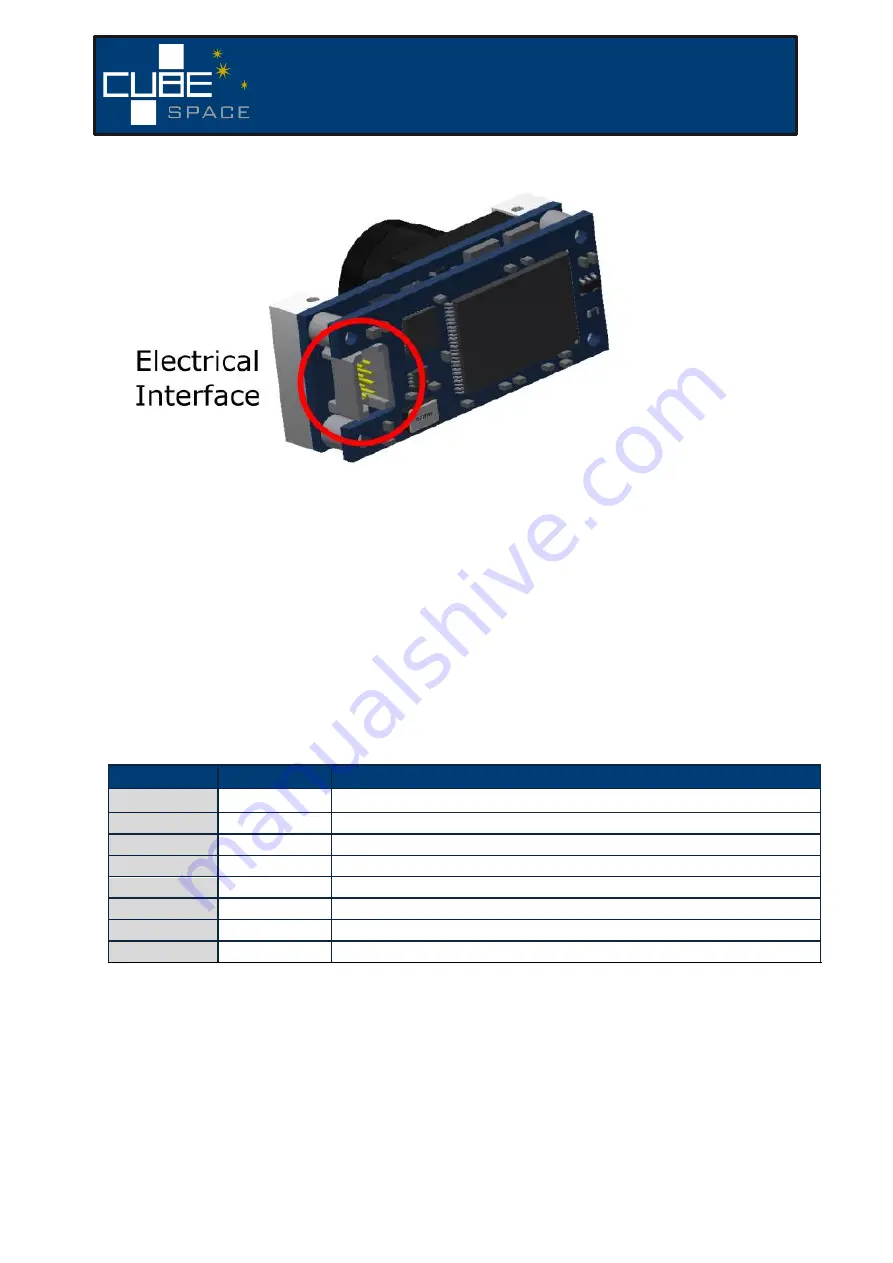
Figure 1
–
CubeSense electrical connections
2.4.1
Power
The CubeSense module draws its power from the USB port if the Support PCB is used. If the
module is not used with the Support PCB, the power could also be provided by a stable lab
power supply with a 3.3V output. The current limit of the supply should be set to
approximately 300mA. Although the CubeSense circuitry has some protection, it is still good
practice to have this current limit. The standard connector populated on the CubeSense
module is a
Samtec TFC-104-01-F-D.
The 3V3 power is located at pin 1 as shown in Table 1.
Table 1
–
Pinout of CubeSense Connector
*
Pin
Name
Description
1
3.3V
Input voltage of 3.3V
2
SDA
1
SDA line for I2C communication
3
SCL
1
SCL line for I2C communication
4
GND
Ground pin (both ground pins must be used)
5
RX
RX line for UART communication
6
TX
TX line for UART communication
7
EN
Enable line that turns the CubeSense on or off (active high)
8
GND
Ground pin (both ground pins must be used)
1
There are no pull-up resistors on the I2C bus. Any pull-up resistor should be implemented by the master.
2.4.2
Communication
There are multiple options for communicating with CubeSense. The primary communication
method for ground testing is UART. The location of the UART TX and RX pins are shown in
Table 1.


