Electrical System
93
11.
Remove screws securing the right pod by following
the procedures described in Chapter 2: Body.
NOTE:
Do not remove the pod.
NOTE:
Do not disconnect the battery pack while
removing the right pod.
12.
Lift the pod enough to gain access to the key switch.
13.
Push the PTO switch in to the “OFF” position.
14.
Turn the key switch to the “ON” position
15.
Place the negative probe of the DMM in the socket
of pin 7 on the 12 pin breakout adapter.
16.
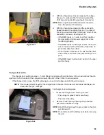
While watching the DMM, back probe the red wire
with a white trace at B-Com of the PTO switch.
See Figure 5.68.
17.
Back probe the red wire with a white trace at C-Com of the PTO switch.
•
If the DMM reads 4 - 5 volts, the signal from the VCM is reaching both circuits of the PTO switch.
•
If the DMM reads 0 volts at one or both of the Com tabs, there is a fault in the harness.
18.
While watching the DMM, back probe the black wire with a white trace at B-N.O of the PTO switch.
19.
Back probe the white wire with a black trace at C-N.O. of the PTO switch.
•
If the DMM reads 4 - 5 volts at one or both of the N.C. tabs, there is a short. Remove the PTO switch and
bench test it. If the switch is functional, the short is in the harness.
•
If the DMM reads 0 volts at both of the N.C. tabs, continue to step 20.
20.
Pull the PTO switch out to the “ON” position.
21.
While watching the DMM, back probe the black wire with a white trace at B-N.O of the PTO switch.
22.
Back probe the white wire with a black trace at C-N.O. of the PTO switch.
•
If the DMM reads 4 - 5 volts at both positions, the PTO switch is functional, the harness is faulty.
•
If the DMM reads 0 at either or both positions, the PTO switch is faulty.
Figure 5.68
PTO switch
Содержание RZT-S Zero
Страница 2: ......
Страница 42: ...RZT S Zero 38 ...
Страница 112: ...RZT S Zero 108 ...
Страница 154: ...NOTES ...
Страница 155: ......
Страница 156: ...MTD Products Inc Product Training and Education Department FORM NUMBER 769 08008 02 05 2013 ...


