Body
21
3d.
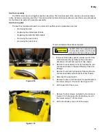
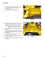
Remove the four screws that hold the control
panel bracket to the mower using a 3/8”
wrench. See Figure 2.37.
3e.
Lift the control panel and the bracket off of the
mower.
4.
Fish the harnesses through the holes in the rear sec-
tion.
NOTE:
If the front main and the rear sections are being
removed as one assembly, skip to step 6.
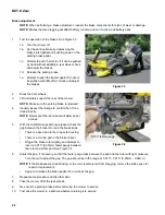
5.
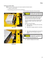
Remove the three screws, one on the left and two on
the right, that hold the rear seat box section to the
front main section using a 1/2” wrench.
See Figure 2.38.
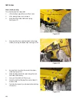
6.
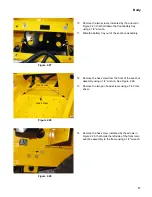
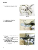
Remove the screw that holds the right rear finger
guard to the frame using a 1/2” wrench.
See Figure 2.39.
7.
Slide the finger guard off of the mower
Figure 2.37
! CAUTION
! CAUTION
Do not remove the controller cov-
ers. There are precharge capaci-
tors inside each of the controllers.
These capacitors will hold a charge large enough to
shock the technician and/or damage the controller
even after the batteries are disconnected.
Figure 2.38
Left
Right
Figure 2.39
Right rear finger guard
Содержание RZT-S Zero
Страница 2: ......
Страница 42: ...RZT S Zero 38 ...
Страница 112: ...RZT S Zero 108 ...
Страница 154: ...NOTES ...
Страница 155: ......
Страница 156: ...MTD Products Inc Product Training and Education Department FORM NUMBER 769 08008 02 05 2013 ...


