S E C T I O N 3 : O P E R A T I O N
M N X 1 0 0 1 1 R E V C
●
7 / 3 0 / 2 0 1 8
9
Connection Technology Center, Inc.
●
7939 Rae Boulevard
●
Victor, NY 14564
●
(585) 924-5900
COUPLING TIME CONSTANT
A feature of this system is that power to operate the internal IC in the sensor and the signal
from the sensor both flow over the same pair of wires. The DC bias from the sensor amplifier is
blocked by a 10 µF capacitor in the power unit while the AC or dynamic signal is allowed to pass
through this blocking capacitor to the output jack.
The value of the coupling capacitor and the resistive load of the readout instrument (in parallel
with the pulldown resistor) determine the discharge time constant of the power unit/readout
combination and set the low frequency performance of this system.
NOTE: The discharge time constant of the sensor itself must be considered also but for this guide, we
will concentrate on the effect of the power unit/readout combination only. The operating guide
supplied with the sensor will address the low frequency response of the sensor.
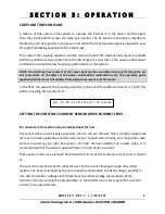
In the PS12 the value of the coupling capacitor is 10µF and the pulldown resistor is 1 MΩ. This
yields a coupling time constant of:
SETTING THE CONSTANT CURRENT SENSOR DRIVE CURRENT LEVEL
For most users, this section may be skipped over for now.
The sensor drive current levels are factory set at 5 mA per channel. This is a high enough level
for most normal applications and should only be changed when driving very long cables with
sensors measuring very high frequencies. For best thermal stability and lowest noise, it is
recommended that the sensors operate from 2 to 5 mA of drive current.
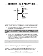
These power units use a clamped base transistor circuit as the constant current source. (Figure
3).
The constant current out of the collector is set by the current flowing through the emitter
resistor. The base is clamped by the zener/resistor combination to a fixed voltage, and this in
turn sets the emitter voltage via the fixed base to emitter voltage characteristic of the
transistor. Thus by varying the potentiometer in the emitter circuit, we may set the constant
current to any desired level.
Eq 1. TC = RC = 1 x 10
6
x 10 x 10
-6
= 10 Seconds


