background image

24

CTC 380 S 

General information

Protection 

When using Protection, the heating system is off. But it remains protected 

against frost (frost protection temperature), provided there is no power 

failure. 

Eigenschaften des Schutzbetriebs:

•  Heating off 

•  Temperature according to frost protection

•  Protective functions active 

•  Automatic summer / winter changeover (ECO functions) 

and automatic 24-hour heating limit active

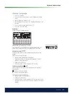
Selecting DHW heating mode

The button is used to switch DHW heating mode on and off. The choice is 

indicated by a bar which appears below the symbol..

Trinkwasserbetrieb 

•  On

The DHW is heated according to the selected switching program.

•  Off

No DHW heating, the protective function is active.

Trinkwasser-Push

To do this, keep the DHW operating mode button depressed for at least 3 

seconds. 

The DHW push can also be started when:

•  The operating mode is “Off“ 

•  Operating mode changeover acts via H1 or centrally (LPB) 

•  All heating circuits have assumed the holiday mode

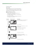
Adjusting the room temperature 
setpoint

Turn the setting knob to increase or decrease the Comfort setpoint.

For the Reduced setpoint

•  Press the OK button

•  Choose operating page ”Heating circuit” and

•  Adjust the ”Reduced setpoint”.

Each time you make a readjustment, wait at least 2 hours, allowing the 

room temperature to adapt.

Содержание 380 S 18

Страница 1: ...ding sustainable energy solutions worldwide Installation and maintenance instruction CTC 380 S Model 18 22 27 33 40 50 63 161 505 41 4 2015 11 19 IMPORTANT READ CAREFULLY BEFORE USE KEEP FOR FUTURE REFERENCE ...

Страница 2: ......

Страница 3: ...nce Fill in the information below It may be useful if anything should happen Product Manufacturing No With reservation for typing errors Subject to alterations in design Plumber Name Date Telephone No Electrician Name Date Telephone No Chimney sweep Name Date Telephone No 161 505 41 2 2013 01 14 ...

Страница 4: ...______________________15 2 16 Filling ______________________________________________________________15 2 17 Siphon____________________________________________________________15 2 18 Neutralisation box ____________________________________________15 2 19 Chimney solutions____________________________________________16 3 Electrical installation boiler________________________________ 18 3 1 General inf...

Страница 5: ...evity The CTC 380 S is designed for firing with a minimum of ecologically harmful emissions and energy losses The CTC 380 S is available in seven sizes from 18 63 kW The CTC 380 S supplies the total requirement of heating and DHW of the house The CTC 380 S has in order to simplify the installation water and flue gas connections on the top as well as the rear side of the boiler The CTC 380 S is equ...

Страница 6: ...ase hand over this technical manual to the customer after the installation Safety Instructions The following safety instructions should be followed when handling installing and using the CTC 380 S Ensure that the boiler is currentless before any interventions Do not flush the boiler or any of its control equipment with water The flue gas channel and the ventilation duct of the boiler room for air ...

Страница 7: ...10 110 110 110 Water content l 98 5 98 5 92 92 Weight kg 197 197 200 5 210 Number of turbulators Pcs 6 6 9 9 Turbulator model 21 45 27 45 27 45 21 45 Electrical data 230V 1N 230V 1N 230V 1N 230V 1N 1 Technical information 1 1 Technical data 3 stroke oil heating boiler CTC 380 S Model 40 50 63 Rated output kW 39 7 51 2 61 6 Rated input kW 42 7 55 1 66 9 Oil supply kg h 3 6 4 65 5 65 Flue gas mass l...

Страница 8: ...low rear R 1 18 33 3b Primary flow rear R 1 40 63 4a Return flow rear R 1 18 33 4b Return flow rear R 1 40 63 5 Expansion connection R 1 6 Drainage R 1 7a Flue gas outlet top 130 mm 18 33 7b Flue gas outlet top 150 mm 40 63 8 Basic unit Siemens RVS13 143 9a Operator unit Siemens AVS37 294 9b Power pack Siemens AVS16 290 10 Adjustable feet M10 11 Flue gas outlet rear Output sizes in kW ...

Страница 9: ...ler water All sizes are from factory equipped with for each size adapted standard turbulators The turbulators are reached behind the cleaning door in the front of the boiler Adjustable feet The boiler is equipped with four adjustable feet Basic unit The basic unit of the Comfort control Siemens RVS43 143 For more information see the part Electrical installation Comfort control Heat insulation In o...

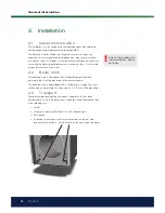
Страница 10: ...id oxygen enrichment of the system 2 2 Boiler room The boiler room must correspond to existing building regulations and particularly then the firing regulations of the present country The boiler room must be equipped with a venthole for air supply The cross section area of the venthole must be at least 6 5 cm2 pro 1 kW boiler output 2 3 Transport To avoid transport damage do not unpack the boiler ...

Страница 11: ...he handling do not unpack the boiler until it has reached its site in the boiler room After the unpacking check that the boiler has not been damaged during transport Report eventual transport damages to the transporter Standard delivery Oil condensing boiler CTC 950 IC Condens Safety valve Siphon Primary flow sensor Outdoor sensorDHW storage tank sensor 2 5 Boiler stand Accessory kit The boiler st...

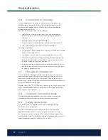
Страница 12: ... chimney must feasible actions be taken to secure that no condensate can flow back to the boiler condensate trap 2 7 Flue gas temperatures When a new boiler is being connected to an old chimney the chimney is often not dimensioned to the new high efficiency of the boiler which may easily result in condensation in the chimney depending on lower flue gas temperatures In order to ventilate the chimne...

Страница 13: ...ion Comfort Control 2 12 Connection domestic hot water DHW Secondary heating circuit The connections located on the rear side of the boiler makes it possible to connect the boiler to a secondary heating circuit These connections offer also the possibility to connect the boiler to a water heater system The temperature of the return flow to the boiler must not be lower than 45 C 2 13 Drainage Drain ...

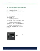
Страница 14: ...arth 3 3 Main switch A main switch should be installed 3 4 Heating circuit pump The heating circuit pump for the heating system is being connected to the connection terminal on the basic unit The switch for the pump is placed on the comfort control of the boiler 3 5 Heating circuit mixing valve The heating circuit mixing valve for the heating system is being connected to the connection terminal on...

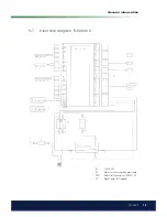
Страница 15: ...15 CTC 380 S General information 3 7 Electrical diagram E 582450 Si Fuse 6 3AT S1 Mains switch with green glow lamp STB Safety limit thermostat STB 110 C H1 Signal lamp SLT tripped ...

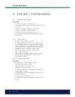
Страница 16: ... the time of the day and date Further adjustments for personal requirements are performed according to the technical manual of the Comfort control See also the part Electrical installation Comfort control Check that the oil burner starts When the boiler has reached its operating temperature check and adjust the oil burner in accordance with its technical manual See also the part Oil burner 4 3 Aft...

Страница 17: ...of the settings of the Comfort control Check control of the temperature of the heating boiler primary flow and flue gas Check control of the burner according to the instructions manual for the burner In a closed system check control of the safety valve by means of turning the regulation device of the valve Check if water run out from the safety valve drain pipe Neutralisationbox Check its function...

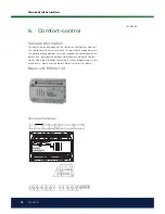
Страница 18: ...Terminal markings General information The boiler is factory equipped with the Comfort control Siemens Albatros2 The Comfort control consists of a basic unit power pack and operator unit The power pack and operator unit creates together the control panel of the boiler Part 6 describes the principal information concerning the Comfort control Fore more information concerning functions programming sys...

Страница 19: ...ge on Input burner fault Input burner stage 1 hours run P AGP8S 07A 109 SK1 SK2 Safety loop Safety loop Q AGP8S 02E 109 N Q3 Neutral conductor Protective earth DHW charging pump diverting valve R AGP8S 03A 109 N Q2 Neutral conductor Protective earth 1st heating circuit pump S AGP8S 03B 109 Y1 N Y2 1st heating circuit mixing valve opening Neutral conductor Protective earth 1st heating circuit mixin...

Страница 20: ...91 109 DB MB LPB data LPB ground a AGP4S 02H 109 CL CL Room unit 2 data Room unit 2 ground b AGP4S 02A 109 CL CL Room unit 1 data Room unit 1 ground b AGP4S 02A 109 AGP4S 03D 109 G Room unit power supply 12V B2 M Boiler sensor Ground f AGP4S 02B 109 B3 M DHW sensor top Ground h AGP4S 02C 109 B9 M Outdoor sensor Ground k AGP4S 02D 109 H1 M Digital 0 10V input Ground n AGP4S 02F 109 B1 M Flow sensor...

Страница 21: ...Phase AC 230 V brown Protective earth green yellow N Neutral conductor blue Connection to basic unit Terminal Name 1 L Phase AC 230 V basic unit brown 2 Protective earth green yellow 3 N Neutral conductor blue 4 L1 Phase AC 230 V burner black 5 S3 Input burner fault Si Fuse 6 3AT S1 Mains switch with green glow lamp STB Safety limit thermostat SLT 110 C H1 Signal lamp STB tripped ...

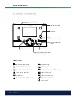
Страница 22: ... and settings Display choices Heating to the Comfort setpoint Info level activated Heating to the Reducted setpoint Programming activated Heating to the frost protection setpoint Heating function temporarily off ECO function activ Process running please wait Holiday function active Change battery Reference to heating circuit Burner in operation only oil gas burner Maintenance special mode Error me...

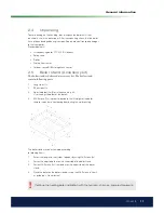
Страница 23: ...hich appears below the symbols Automatic mode Automatic mode controls the room temperature according to the time program Characteristics of automatic mode Heating mode according to the time program Temperature setpoints according to heating program Comfort setpoint or Reduced setpoint Protective functions active Automatic summer winter changeover ECO functions Continous operation or Continous oper...

Страница 24: ...elow the symbol Trinkwasserbetrieb On The DHW is heated according to the selected switching program Off No DHW heating the protective function is active Trinkwasser Push To do this keep the DHW operating mode button depressed for at least 3 seconds The DHW push can also be started when The operating mode is Off Operating mode changeover acts via H1 or centrally LPB All heating circuits have assume...

Страница 25: ... Other displays Room temperature Outside temperature min State DHW Date and time of day Room temperature minimum Outside temperature max State boiler Telephone customer service Room temperature maximum DHW temperature 1 Boiler temperature State heating circuit 1 Outside temperature State heating circuit 2 Exceptional cases In exceptional cases the display shows one of the following symbols Error m...

Страница 26: ...ture controller TR Setpoint adjustment with manual control After manual control has been activated a change to the basic display must be made There the maintenance special mode symbol appears Setpoint adjustment with manual control Press the Info button to switch to info display Manual mode where the setpoint can be adjusted Chimney sweep function The chimney sweep function is activated by a short...

Страница 27: ...ally return to the basic display Operating lines may be hidden depending on the type of unit their configuration and user level Operation Display example Description 1 0 4 8 12 16 20 24 AUTO 2359Z140 Roomtemperature You see the basic display If the basic display is not shown press the ESC button to return to it Press the OK button 2 Text3 0 4 8 12 16 20 24 AUTO 2359Z140 Operator section Timeof day...

Страница 28: ...59Z140 Timeof dayanddate Hours minutes 5 Turn the setting knob until the hours of the time of day are correct To confirm press the OK button 5 0 4 8 12 16 20 24 AUTO 2359Z140 Time of day anddate Hours minutes 6 The display shows the minutes flashing Turn the setting knob until the minutes of the time of day are correct To confirm press the OK button 6 0 4 8 12 16 20 24 AUTO 2359Z140 Timeof dayandd...

Страница 29: ... user level Enduser Press the Info button for 3 seconds 3 Text3 0 4 8 12 16 20 24 AUTO 2359Z140 Commissioning Enduser You are given a choice of user levels Turn the setting knob until the required user level is reached Press the OK button Text3 0 4 8 12 16 20 24 AUTO 2359Z140 Operator section Timeof dayanddate You are now on the required user level To reach the OEM level enter the relevant code Us...

Страница 30: ...user 2359Z139 OEM Enduser Commissioning Heating engineer Time of day and date Operator section Wireless Time program heatingcircuit 1 Time program heatingcircuit 2 Time program heatingcircuit P Holidays heating circuit 1 Diagnosticsofconsumers Hours minutes Month day Year Start of summer time End of summer time Hours 1 24 h Minutes 0 60 min Setting structure for Enduser The example given here show...

Страница 31: ... at least 3 seconds and select operating level Commissioning with the setting knob Then press the OK button Make the functional check as described below Reset the attenuated outside temperature operating page Diagnostics of consumers operating line Outside temp attenuated line 8703 Functional check To facilitate commissioning and fault tracing the controller allows output and input tests to be mad...

Страница 32: ... button Select Time prog heating circuit 1 and press OK The text Preselection is shown Press OK and the selection start flashing You can select between program for Mo Su Mo Fr Sa Su or each day separately Select 1 st phase on and press OK The time start flashing and you can select the start time for heating comfort setpoint Press OK Select 1 st phase off and press OK The time start flashing and yo...

Страница 33: ...eating curve slope requires readjustment Increase adjustment Raises the flow temperature especially when outside temperatures are low Decrease adjustment Lowers the flow temperature especially when outside temperatures are low Default setting 1 5 Parallel displacement of the heating curve is used to change the flow temperature evenly across the entire outside temperature range or in other words if...

Страница 34: ... temp min to a higher temperature Notice that the value for Summer winter setpoint stops the heating circuit at chosen temperature in Automatic mode So you maybe have to select a higher temperature on this as well To select a value for the set points do as follow Press the OK button Press the i button for 3 seconds Select Commissioning and press OK Select Heating circuit 1 and press OK Select Flow...

Страница 35: ...e 1 sensor error 6 65 Room temperature 2 sensor error 6 68 Room temperature 3 sensor error 6 70 Buffer storage tank temperature 1 sensor error 6 71 Buffer storage tank temperature 2 sensor error 6 72 Buffer storage tank temperature 3 sensor error 6 73 Collector temperature 1 sensor error 6 74 Collector temperature 2 sensor error 6 81 Short circuit LPB 6 82 LPB address collision 3 83 BSB wire short...

Страница 36: ...active 6 174 Alarm contact 4 H3 active 6 176 Upper pressure limit 2 crossed 6 177 Critical lower pressure limit 2 crossed 6 178 Temperature limiter heating circuit 1 3 179 Temperature limiter heating circuit 2 3 217 Sensor error common message 6 218 Pressure supervision common message 6 243 Swimming pool temperature sensor error 6 320 DHW charging temperature sensor error 6 321 Instantaneous DHW h...

Страница 37: ...no function 3 339 Collector pump Q5 missing 3 340 Collector pump Q16 missing 3 341 Collector sensor B6 missing 3 342 Solar DHW sensor B31 missing 3 343 Solar integration missing 3 344 Solar controlling element buffer K8 missing 3 345 Solar controlling element swimming pool K18 missing 3 346 Solid fuel boiler pump Q10 missing 3 347 Solid fuel boiler comparison sensor missing 3 348 Solid fuel boiler...

Страница 38: ...et standard values for set points time program and operating modes Though is it prerequisited to make settings of the time of the day and date Further adjustments for personal requirements are performed according to the technical manual of the Comfort control 3 See also the part Electrical installation Comfort control 4 Check that the oil burner starts 5 When the boiler has reached its operating t...

Страница 39: ...el in the tank Check control of the settings of the Comfort control Check control of the temperature of the heating boiler primary flow and flue gas Check control of the burner according to the instructions in the technical manual from the manufacturer In a closed system check control of the safety valve by means of either turning or lifting the regulation device of the valve Check if water run ou...

Страница 40: ...ation must be regularly cleaned according to existing regulations 9 6 Drainage The boiler must be currentless upon drainage The drainage connection drain valve is low located on the rear side of the boiler By drainage of the whole system must the heating circuit mixing valve be fully open In a closed system air must be supplied 9 7 Oil operation General information Adjustments and maintenance of t...

Страница 41: ...n the technical manual of the burner Boiler disturbance The safety limit thermostat has released Reset by pressing the button on the power pack See also Electrical installation Power supply to boiler disconnected Check the fuse on the power pack Check if the mains switch on the power pack is switched on See also Electrical installation Unsufficient room heating Check the settings of the Comfort co...

Страница 42: ...42 CTC 380 S General information ...

Страница 43: ...43 CTC 380 S General information ...

Страница 44: ...Enertech AB P O Box 309 SE 341 26 Ljungby Sweden www ctc se www ctc heating com 161 505 41 2 2013 01 14 ...

Отзывы: