English |
9
2 610 A12 214 • 22.7.09
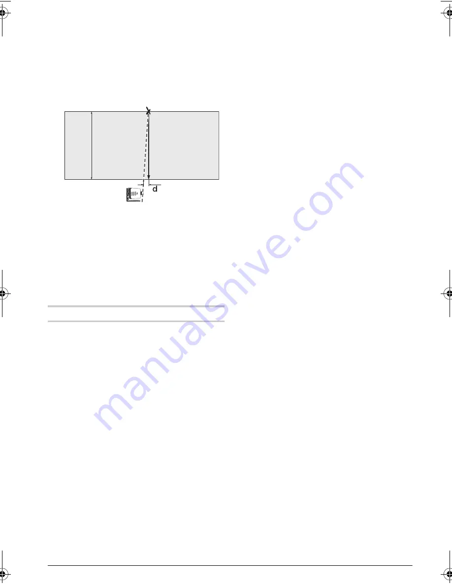
Checking the Levelling Accuracy in the Vertical
Position
A free measuring distance of 10 m on a firm surface in
front of a wall is required for the check. Fasten a
plumb bob rope to the wall.
– Mount the measuring tool in the vertical position
onto a tripod, or place it on a firm and level surface.
Align the measuring tool accurately with the spirit
level and switch it on.
– Align the measuring tool such that the laser beam
impinges centrally on the plumb bob rope at the
upper end. The difference
d
between laser beam
and plumb bob rope at the bottom end of the rope
results in the deviation of the measuring tool to the
vertical line.
For a 10 m high measuring distance, the maximum
allowable deviation is:
10 m x
±
0.2 mm/m =
±
2 mm.
Thus, the difference
d
must not exceed 2 mm.
Working Advice
f
Always use the centre of the laser point for
marking.
The size of the laser point changes with
the distance.
Laser Viewing Glasses (Accessory)
The laser viewing glasses filter out the ambient light.
This makes the red light of the laser appear brighter
for the eyes.
f
Do not use the laser viewing glasses as
safety goggles.
The laser viewing glasses are
used for improved visualisation of the laser beam,
but they do not protect against laser radiation.
f
Do not use the laser viewing glasses as sun
glasses or in traffic.
The laser viewing glasses
do not afford complete UV protection and reduce
colour perception.
Working with the Laser Receiver (Accessory)
(see figure C)
Under unfavourable light conditions (bright environ-
ment, direct sunlight) and for larger distances, use the
laser receiver for improved finding of the laser beam
25
.
When working with the laser receiver, select rotational
operation with the highest rotational speed.
Before working with the laser receiver, read and
observe the laser receiver operating instructions.
Working with the Remote Control (Accessory)
When pressing the operating controls, it is possible to
bring the measuring tool out of its level position. This
effect is prevented by using the remote control
27
.
The receiption lense
11
for the remote control is
located on the front side of the measuring tool.
For information on working with the remote control
27
,
see “Remote control”, page 12.
Working with the Tripod (Accessory)
The measuring tool is equipped with a 5/8" tripod
mount
5
each for horizontal and vertical operation.
Place the measuring tool via the tripod mount
5
onto
the 5/8" male thread of the tripod and screw the lock-
ing screw of the tripod tight.
Adjust the tripod roughly before switching on the
measuring tool.
Working with Wall Holder/Alignment Unit
(Accessory) (see figure B)
You can also mount the measuring tool to the wall
mount with alignment unit
26
. For this, screw the 5/8"
screw of the wall mount into one of the tripod mounts
5
of the measuring tool.
Fasten the wall holder
26
with the clamping screws to
stable, as level or vertical as possible objects, with a
max. thickness of 6 mm.
Mounting to a wall: Mounting to a wall is recom-
mended, e.g., for work above the elevation height of
tripods or for work on unstable surfaces and without
tripod. For this, fasten the wall holder
26
, with the
measuring tool mounted, as vertical as possible to a
wall.
Horizontal assembly: The wall holder can ease the
alignment of the vertical laser plane to a reference line.
For this, fasten the wall holder horizontally and mount
the measuring tool in vertical position.
With the alignment unit, the mounted measuring tool
can be moved vertically (when mounted to the wall) or
horizontally within a range of approx. 17 cm.
Working with the laser target plate (Accessory)
With the laser target plate
24
, the laser mark can be
projected on the ground/floor or against a wall. With
the magnetic holder, the laser target plate can also be
fastened to ceiling constructions.
With the zero field and the scale, the offset or drop to
the required height can be measured and projected at
another location. This eliminates the necessity of pre-
cisely adjusting the measuring tool to the height to be
projected.
The laser target plate
24
has a reflecting coating
which improves the visibility of the laser beam from a
larger distance or in case of strong sun rays. The lumi-
nosity can be recognized only if you look to the laser
target plate in parallel to the laser beam.
10
m
OBJ_BUCH-1045-001.book Page 9 Wednesday, July 22, 2009 10:40 AM
Содержание Berger Lasermark Wizard LM30
Страница 1: ...en Original instructions Manual Horizontal Vertical Rotary Laser LM30 LM30...
Страница 2: ...2 2 610 A12 214 22 7 09 LM30 1 2 10 8 9 6 5 20 7 2 4 5 3 22 19 16 17 18 14 15 13 12 11 21...
Страница 3: ...3 2 610 A12 214 22 7 09 23 25 24 26 27 C A B...
Страница 4: ...4 2 610 A12 214 22 7 09 29 28 30 31 32 33 34 RC30...


