background image

Crystal Vision 


Using the front control panel 

Up-and-down User Manual R2.5 

18


     18/03/2009 

To continue with control panel operation or configuration, press the CAL key once. A 
second press of the CAL key will return to Statesman control.  

The control panel will display the name of the card that first responds to the polling 
request together with its location number. 

The location number consists of the frame number plus the card position in the frame. 

Navigating the display 

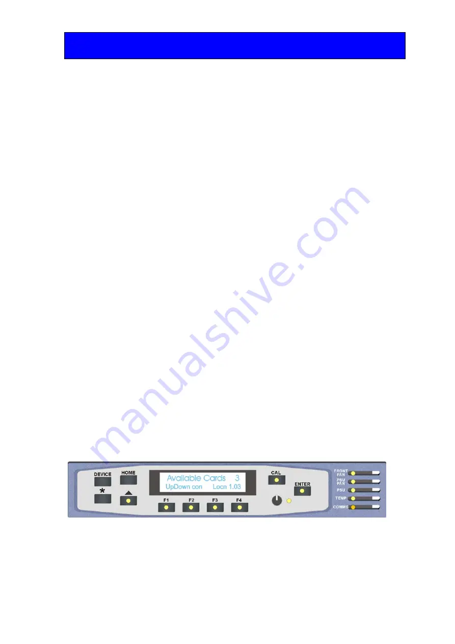
The functions assigned to control panel keys are: 


DEVICE – enters Device menu to select a card or show cards available / enters Panel 
setup when held down during power up / shows frame status when pressed from 
Statesman mode 


CAL – enters or leaves Statesman mode / enters panel diagnostics mode when held down 
during power up / updates the display 


Asterisk – enters board rename menu from the Device menu 


F1 to F4 – soft keys, function assigned within each menu 


HOME – moves the display to the home menu 


ENTER – accept current selection 


Upward arrow – used to move up the menu structure / enter lock panel menu from the 
Device menu 


Rotary control – shaft encoder used to select options or variable data  


Note: 

Please refer to the Crystal Vision Control Panel manual for details of the Panel Setup, Lock Panel and 
Diagnostic menus. 

Selecting Up-and-down 

To select a particular card in a frame, press the DEVICE key to go to the Device menu. 
Note, there may be a delay whilst the frame is interrogated during which time the ‘No 
cards Found’ could be displayed. 

The top line of the display will show ‘Available Cards X’, where X is the number of cards 
that have responded so far to the polling request. 

The available cards menu 

Rotate the shaft encoder and the bottom row will display the successfully polled cards by 
name and location or slot number. 

In the example above, the card displayed is located in the first frame in slot number 3. 

When the desired card is selected press the ENTER key to access that card’s HOME 
menu. The message shows that an Up-and-down has been selected. 

Содержание Up-and-down

Страница 1: ...Technology Park Station Road East Whittlesford Cambridge CB22 4WL England E mail sales crystalvision tv Website www crystalvision tv Tel 44 0 1223 497049 Fax 44 0 1223 497059 Up and down Combined up d...

Страница 2: ...dge operation 11 3 1 Card edge controls 11 3 2 Card edge buttons 11 3 3 Card edge rotary control 11 3 4 Reading card edge LEDs 12 3 5 Navigating card edge menus 12 3 6 Card edge configuration 13 Menu...

Страница 3: ...sman operation 24 Detail Enhancement 25 Reset factory defaults 26 Gains and Offsets 26 6 Trouble shooting 27 6 1 Card edge status LEDs 27 Basic fault finding guide 27 7 Specification 28 Revision 2 Ver...

Страница 4: ...d program Up and down converter The main features are as follows Combined up down and cross conversion Motion adaptive video de interlacing with both detail and edge enhancement Flexible aspect ratio...

Страница 5: ...quality Up and down automatically enters a bypass mode when the input is the same as the selected output standard This is achieved by bypassing the major processing blocks Whilst in bypass the gain o...

Страница 6: ...horizontally stretched to 16 9 monitor width Full source height mapped to monitor height No picture lost but possible significant distortion Full 16 9 source width mapped to 4 3 monitor width Full so...

Страница 7: ...up to two single height modules Note For details of fitting rear connectors please refer to the appropriate frame manual Rear module connections with RM34 The RM34 being the rear module of choice is a...

Страница 8: ...HD SDI OUT Scaler serial digital output HD SDI OUT Scaler serial digital output HD SDI IN LOOP High Definition Standard Definition serial digital input reclocked loop through HD SDI IN LOOP High Defi...

Страница 9: ...3 19 3 20 3 21 4 22 4 Table shows pin number remote number Slot no a pin b pin c pin d pin e pin f pin 1 8 5 9 5 18 5 26 5 19 6 20 6 2 7 5 16 5 17 5 25 5 10 6 11 6 3 8 7 9 7 18 7 26 7 19 8 20 8 4 7 7...

Страница 10: ...emote 4 are 26 way high density D Type male plugs and frame ground is pin 6 in each case and 5V 500mA is pin 15 on Remote 2 Note The 5V output is protected by self resetting thermal fuses which limit...

Страница 11: ...1 8 1 9 1 18 1 26 1 19 2 20 2 2 7 1 16 1 17 1 25 1 10 2 11 2 Table shows pin number remote number Note Remote 1 26 way high density D Type female socket Frame ground is pin 2 and 5V 500mA is pin 1 Re...

Страница 12: ...buttons The Up and down is fitted with two tactile push button switches that allow the operator to navigate within the menu structure Button Function Normal state Up Action Down Up Menu Push to jump u...

Страница 13: ...is out of specification Yellow No function at present Green No function at present 3 5 Navigating card edge menus To access the card edge menu system proceed as follows Press the up arrow until a top...

Страница 14: ...Up and down User Manual R2 5 13 18 03 2009 3 6 Card edge configuration Menu Tree Tip To reach the top menu push the button repeatedly until a top menu is reached Rotate the SCROLL control anti clockw...

Страница 15: ...el affixed to the PCB connector Setting the output configuration Control Output Standard From the CONTROL top menu press ENTER then SCROLL to access either the Output standard Aspect Ratio selection o...

Страница 16: ...o monitor height Significant picture loss Compromise Full 4 3 source width compressed to central 87 5 of 16 9 source width Central 87 5 of source height stretched to monitor height Vertical black band...

Страница 17: ...ate SCROLL to show RGain and press ENTER to select Rotate ADJ shaft encoder to set the R amplitude 80 to 120 Example RGain 100 G Gain Rotate SCROLL to show GGain and press ENTER to select Rotate ADJ s...

Страница 18: ...cleared prior to using the panel for the first time At power up the two line 20 character screen will display Crystal Vision followed by the firmware version number for the control panel All eight co...

Страница 19: ...each menu HOME moves the display to the home menu ENTER accept current selection Upward arrow used to move up the menu structure enter lock panel menu from the Device menu Rotary control shaft encode...

Страница 20: ...d down module are obtained by pressing the F1 F4 keys from the HOME menu Menu keys are illuminated when active and when further menus are available The top level menus are Video controls Output format...

Страница 21: ...r to set the new value Standard Definition 1280 x 720p 1920 x 1080i Press enter to accept the new value Rotate shaft encoder to select the Aspect Ratio Press F2 to select to change the value Rotate sh...

Страница 22: ...set Parameter Default value Gains and levels 100 Output format Standard definition Aspect Ratio Anamorphic Detail 0 Gains and Offsets Pressing F3 from the home menu will bring up the Gains and Offset...

Страница 23: ...o select value 80 120 Press enter to accept the new value Rotate shaft encoder to select Green Offset Press F2 to select to change the value Rotate shaft encoder to select value 80 120 Press enter to...

Страница 24: ...input Up and down status menu Description From the Home menu press F4 to select the status menu which is then traversed by rotating the shaft control Rotate the shaft control to view the video input s...

Страница 25: ...ive panel or REMIND remote control panel must be fitted to allow for Statesman control 5 1 Statesman operation The initial view will show an Explorer style view of the connected frames and modules Dou...

Страница 26: ...ed by checking the appropriate radio button see chapter 1 for a pictorial explanation of the different aspect ratios available These controls will be inoperative and greyed out whilst in bypass mode D...

Страница 27: ...tton will return all parameters to their factory default levels Parameter Default value Gains and levels 100 Output format Standard definition Aspect Ratio Anamorphic Detail 0 Gains and Offsets RGB pi...

Страница 28: ...rmation when trouble shooting Basic fault finding guide The Power OK LED is not illuminated Check that the frame PSU is functioning refer to the appropriate frame manual for detailed information There...

Страница 29: ...SDI 270Mb s to 1 485Gb s serial digital compliant to SMPTE 259M and SMPTE 292M HD Up to 140m with Belden 1694 or equivalent Belden 8281 or equivalent up to 100m SD 270Mb s 250 metres Outputs Number an...

Отзывы: