background image

Crystal Vision 


Maintenance 

Note: 

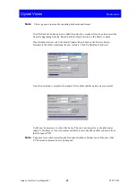
This is a generic tool used for updating both cards and frames. 


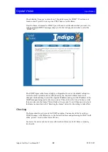
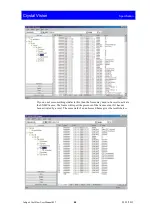
Click 'Refresh list' button and wait whilst the network is scanned. Once done then select the 

frame for upgrading from the 'Board to talk to' drop-down list by IP address or name. 

If not already selected, select the Board Updater tab and click on the Browse button. 

Navigate to the folder containing the new software. Click 'Update Board' and wait. 


Once the download is complete the updater will confirm that the update was successful. 


It will now be necessary to reboot the frame. This can be achieved by cycling the mains 

supply to the frame or if not convenient carefully remove the ribbon cable connector from 

the front panel PCB. 

Note: 

Take great care when reinserting the front panel ribbon cable that none of the pins in the 

PCB connector become bent or misaligned.  


Indigo 4 CoolFlow User Manual R1.7


38


03/12/2012 

Содержание Indigo 4 CoolFlow

Страница 1: ...k Station Road East Whittlesford Cambridge CB22 4WL England E mail sales crystalvision tv Website www crystalvision tv Tel 44 0 1223 497049 Fax 44 0 1223 497059 Indigo 4 CoolFlow 4U frames Includes Indigo 4 CoolFlow and Indigo 4SE CoolFlow ...

Страница 2: ...Input connector Indigo 4SE only 13 RJ45 Ethernet connector 14 2 4 Front panel settings 14 Frame Address 15 Status LEDs 15 Lower Upper slot range 15 Config Switches 16 Default IP address Indigo 4SE only 16 PSU Configuration 16 Setting RS422 frame addresses Indigo 4SE only 17 2 5 Ethernet control 18 Setting up and connecting 18 Status 20 Changing the IP Address 20 Adding a frame serial number 21 Nam...

Страница 3: ...y asked questions 42 5 Appendix 43 5 1 Module addresses and node numbers 43 5 2 SNMP Quick Start Guide 44 6 Specification 48 Revision 1 Reference to Mains Combiner removed Appendix 5 2 SNMP quick start guide added 01 06 10 Revision 2 Redundant power supply warning added 10 06 10 Revision 3 RS422 added to section heading page 17 Reference to mains combiner removed page 28 Flasher red PSU LED note a...

Страница 4: ...Indigo 4 CoolFlow User Manual R1 7 Crystal Vision Revision 7 Notes added concerning fuses Pages 36 39 40 19 11 12 Indigo 4 CoolFlow User Manual R1 7 3 03 12 2012 ...

Страница 5: ... for up to four plug in power supplies The four power supply facility allows for redundancy and continued operation in the event of a power supply failure All models have a hinged front panel that allows easy access to removable fan assemblies power supplies and modules The Indigo 4 CoolFlow frame with front control panel open There are six easily accessible front fans One is fitted on a detachabl...

Страница 6: ...ot meet electromagnetic compatibility EMC requirements in this condition The Indigo PSUs have a built in processor which communicates with the front panel display processor referred to as a PIC and monitors power rail voltage levels 5 75V and 6 0 V The PSUs also store their own serial number in non volatile memory The panel processor regularly receives status updates from the PSU processors about ...

Страница 7: ... Grn Red Door closed and fan idle Door open and fan operational Change PSU fan PSU3 Unlit Grn Red No PSU3 detected Normal operation PSU3 fault PSU1 Unlit Grn Red No PSU1 detected Normal operation PSU1 fault Lower Temp Grn Red Normal operation Internal temperature too high approx 65o C Comms Unlit Flash amber Press Device in Statesman mode for comms status Warning In frames where only two power sup...

Страница 8: ...ront panel open Do not use the frame unless all the rear connector positions are filled either with Crystal Vision rear modules or with Crystal Vision blanking plates Do not operate the equipment with covers or panels removed General To avoid electric shock do not operate this product in wet or damp conditions To avoid injury or fire hazard do not operate this product in an explosive atmosphere On...

Страница 9: ...ail the closed frame can still operate indefinitely with an ambient temperature of 40o C It is also possible to operate the frame with the front panel open however the frame may not meet electromagnetic compatibility EMC requirements in this condition 2 2 Frame connectors The following connectors are available at the rear of the frame Connector Function Notes IEC top Upper PSU AC input 85 to 264V ...

Страница 10: ...cables To connect the Indigo 4 frame to AC mains proceed as follows Power the unit by connecting an IEC power cord s to the upper and or lower IEC connectors depending on the number of installed power supply modules Mains cables must have a minimum current rating of 6A be fitted with an IEC 320 female connector include a protective ground connection and meet relevant local safety standards Tip To ...

Страница 11: ...t upper PSU2 Slot 7 GPI a Relay close on fault PSU4 6 Slot 5 GPI b Frame GND Slot 7 GPI b Frame GND 7 Slot 2 GPI a N C Slot 4 GPI a N C 8 Slot 1 GPI a N C Slot 3 GPI a N C 9 Slot 1 GPI b N C Slot 3 GPI b N C 10 Slot 10 GPI a Slot 2 GPI e Slot 12 GPI a Slot 4 GPI e 11 Slot 10 GPI b Slot 2 GPI f Slot 12 GPI b Slot 4 GPI f 12 Slot 9 GPI b Slot 9 GPI e Slot 11 GPI b Slot 11 GPI e 13 Slot 6 GPI c Slot ...

Страница 12: ...lot 18 GPI b Relay common PSU3 Slot 20 GPI b Relay common PSU1 15 Slot 17 GPI c 5 5V nom dc out Slot 19 GPI c N C 16 Slot 14 GPI b RX bus RS422 Slot 16 GPI b N C 17 Slot 14 GPI c TX bus RS422 Slot 16 GPI c N C 18 Slot 13 GPI c RX RS422 i p Statesman Slot 15 GPI c N C 19 Slot 22 GPI c Slot 13 GPI e Slot 24 GPI c Slot 15 GPI e 20 Slot 22 GPI d Slot 13 GPI f Slot 24 GPI d Slot 15 GPI f 21 Slot 21 GPI...

Страница 13: ...cription pin number Relay common Remote 8 pin 14 Open on fault Remote 8 pin 23 Close on fault Remote 8 pin 5 The PSU alarm relays are grouped in two groups PSU1 and PSU3 relays act together and similarly PSU2 and PSU4 relays act together Should an error occur in the top half of the frame say a front panel fan failure or PSU failure and assuming all PSUs are fitted both relays situated in that half...

Страница 14: ...o 4SE only Pin number Function 1 RX RS422 i p Statesman 2 RX RS422 i p Statesman 3 TX RS422 o p Statesman 4 and 5 Not used 75 ohm resistor to GND in frame 6 TX RS422 o p Statesman 7 and 8 Not used 75 ohm resistor to GND in frame The signals on pins 1 2 3 and 6 are also available on the Remote 6 connector Note Since there is no ground connection via the 422 Bus two frames or other pieces of equipme...

Страница 15: ...he lower position to control the lower section of the frame higher slot numbers See section 2 7 for an explanation of the slot numbers On the upper edge of the front panel PCBs the config switches and status LEDs can be found PCB top edge switches and LEDs Note There are two versions of front panel PCB used in the Indigo 4 CoolFlow these being a full build and part build The PCB in the upper posit...

Страница 16: ...frame address 10 Status LEDs These LEDs are useful for trouble shooting the network link The link LED will be illuminated whenever the frame is connected to a network Should this LED not be lit check the cable connection between the frame and network outlet The data LED flashing will indicate that communications between the frame and the network exists Description Data Flashing This LED will flash...

Страница 17: ...to prevent the long term stressing of the modules Warning Although it is possible to operate the frame with the front panel open the frame may not meet electromagnetic compatibility EMC requirements in this condition Default IP address Indigo 4SE only On the lower front panel PCB switch four in the down position sets the active front panel to the default IP address of 10 0 0 201 This default addre...

Страница 18: ...ame addresses Indigo 4SE only The frame address which only relates to a non passive panel is normally set to zero However unique frame addresses are required in Statesman systems where multiple frames communicate with a single PC port The frame address switch is located on the lower front panel PCB Indigo active remote Statesman panel hardware settings Frame address Note Passive panels do not have...

Страница 19: ...g to a network port hub uses a straight CAT 5 cable To access the internal web page set the frame to the default IP address by setting the default IP address switch DIP4 to down Open up your PC web browser and set its search to http 10 0 0 201 and select go to This is the default IP address the sub mask being 255 255 255 0 After a dialogue box has briefly appeared the Indigo main status page will ...

Страница 20: ...ing the Hex switch setting second line in status list this is the setting of the frame address switch Rotate this switch to something other than the number displayed Refreshing the browser will then reflect this change therefore verifying that the correct frame is being communicated with Indigo 4 CoolFlow User Manual R1 7 19 03 12 2012 ...

Страница 21: ... serial number may also be entered To reset the IP address from the status page select the Network link A new page will open allowing entry of the required IP address and Netmask Enter the new IP address and Netmask information and select Change Should the frame be connected to a DHCP running network and a fixed IP address is not required leave all the information blank and tick the DHCP box befor...

Страница 22: ...ave had a serial number entered during manufacture presently this is the front panel serial number This serial number can be freely overwritten with any series of numbers within the specified range The electronic serial number consists of three groups of numbers These groups must only contain digits with no gaps and must fall into the range of 0 127 An example would be 0 0 0 or 127 127 127 From th...

Страница 23: ...al number has been successfully entered a confirmation dialogue is displayed The Status page will also echo the new serial number Serial number successfully added Naming As well as having a discrete IP address it can be useful to give a frame its own unique name perhaps to reflect its location The naming tab allows this name to be added with up to 20 characters and no spaces Serial number successf...

Страница 24: ...entify a particular host in various forms of electronic communication such as the World Wide Web e mail or Usenet The hostname tab enables such a name to be entered Hostname window Reset The reset button allows the frame front panel to be rebooted remotely such as required when the IP address is changed Reset window Note Restart only affects the front panel and not any other cards within the frame...

Страница 25: ...PSU and frame systems These SNMP traps can then be used to trigger alarms for example when a signal has been removed the video standard changed or any of the many monitored status variables change Note It will be necessary to import the frame MIB into the SNMP manager See the manager instructions if necessary to accomplish this Management information base MIB As is normal for an SNMP manager syste...

Страница 26: ...ent 1 Found Not yet found Frame Present 2 Frame PIC found not found PSU Present 2 Found Not yet found Frame Type 1 Reserved Unknown PSU Present 3 Found Not yet found Frame Type 2 Reserved Unknown PSU Present 4 Found Not yet found Frame Temperature 1 Integer temp PSU Type 1 PSU 160i Unknown Frame Temperature 2 Integer 0 PSU Type 2 PSU 160i Unknown Frame Open 1 Front panel open closed unknown PSU Ty...

Страница 27: ...tus change and its consequences It will be quite common for multiple traps to be sent for any one incident For example removing an input may typically trigger eight traps it will then be down to the SNMP manager to sort these into a hierarchical order or mask as necessary Example of a trap received by the SNMP manager Indigo 4 CoolFlow User Manual R1 7 26 03 12 2012 ...

Страница 28: ...nside of the frame can be accessed to change the modules by pulling forward the two black grab handles one on each side of the front panel The Indigo 4 CoolFlow frame with front control panel open Warning Although the frame can be operated with the front panel open the frame may not meet electromagnetic compatibility EMC requirements in this condition Indigo 4 CoolFlow User Manual R1 7 27 03 12 20...

Страница 29: ...d Inserting modules To insert a module proceed as follows Remove the two screws holding the bracket adjacent to the slot intended for the module and keep both the screws and bracket in a safe place Insert the module into the appropriate guides and push it fully home Refit the retaining brackets if required The Indigo 4 CoolFlow upper frame with two modules fitted in slots 1 and 2 Removing modules ...

Страница 30: ...anical support as well as ensuring EMC compliance To access the rear connector motherboard the appropriate EMC covers and retaining brackets must be removed Fitting rear connectors To fit a rear connector proceed as follows Disconnect the mains power leads from the frame Remove the rear relevant EMC cover s at the rear of the frame by unscrewing the adjacent retaining bars Push fit the selected re...

Страница 31: ...frame is supplied with the 160W rated PSU 160i It is possible to use the older PSU 75i and PSU 150i but it is preferred that these are not mixed in any one frame PSU 160i top view Note Care should be taken if mixing power supply types It is not recommended to combine the PSU 75i with anything other than a second PSU 75i The Indigo power supply modules are not compatible with similar PSUs used in F...

Страница 32: ...d only a single supply be fitted within either the lower or upper section with the switch set to 2 a power supply fault will be registered Warning In frames where only two power supplies are fitted to maintain redundancy the power supplies must be fitted so that they are in alternate positions in both the upper and lower sections of the frame e g upper frame upper position and lower frame lower po...

Страница 33: ...oling mode In Maximum cooling mode both front panel fans in each section run at maximum speed This mode is ideal for equipment bays where noise is not a concern Note Auto mode is dependent on PSUs and PSU fans not being in an alarm state If one of the fans should fail the closed frame can still operate indefinitely with an ambient temperature of up to 40 C Although only one of the fans is essentia...

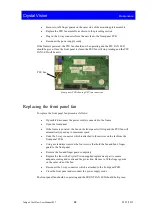
Страница 34: ...e black knobs at either side of the panel Unplug the wiring to front panel PCB Release the captive screw to the left of the PSU fan It will be necessary to use a screwdriver Remove the fan assembly by unclipping the right side from the frame and pull away Note Take care not to damage the panel ribbon cable when removing the fan assembly Once the fan assembly has been unplugged from the front panel...

Страница 35: ...ting the fan assembly To replace the PSU fan assembly proceed as follows Offer up the fan assembly ensuring that the two lugs fit into two slots in the right hand side of the frame Take care not to damage the panel ribbon cable Tighten the captive screw to the left of the PSU fan Connect to the plug on the front panel PCB If the unit was unpowered it may now be powered and tested Replacing the PSU...

Страница 36: ...e frame Open the front panel If the frame is powered the fan on the front panel will stop and the PSU fan will automatically speed up to maximum speed Undo the 3 way connector which is attached to three wires on the fan from the front panel PCB Using a screwdriver remove the four screws that hold the fan and fan s finger guard to the front panel Remove the fan and finger guard completely Replace t...

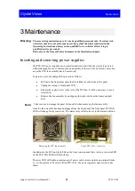
Страница 37: ...om the rear of the frame Using a flat bladed screwdriver or similar tool gently lever out the fuse drawer from the relevant IEC connector using the tab visible at the bottom of the connector depression Whilst levering the fuse holder out support the fuse holder with your free hand to prevent the fuse holder being dropped or lost Remove the defective fuse and replace with either the spare fuse or w...

Страница 38: ...ch powers supplies are no longer functioning by their status LEDs having turning from green to red The red LED present at the front of the power supply will also change from a steady condition to flashing to indicate an error condition If PSU1 and PSU4 are showing a fault condition change the fuse in the lower mains inlet If PSU2 and PSU3 are showing a fault condition change the fuse in the upper ...

Страница 39: ...ton Navigate to the folder containing the new software Click Update Board and wait Once the download is complete the updater will confirm that the update was successful It will now be necessary to reboot the frame This can be achieved by cycling the mains supply to the frame or if not convenient carefully remove the ribbon cable connector from the front panel PCB Note Take great care when reinsert...

Страница 40: ...s scanned Once done then select the frame for upgrading from the Board to talk to drop down list by IP address or name Select the Download licence file tab and click on the Browse button Navigate to the folder containing the Licence file Click Download to Board and wait It will now be necessary to reboot the frame This can be achieved by cycling the mains supply to the frame or if not convenient c...

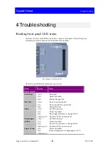
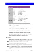
Страница 41: ...or open Normal operation Change the panel fan PSU Fan Unlit Grn Red Door closed and fan idle Door open and fan operational Change PSU fan PSU2 Unlit Grn Red Flashing red No PSU2 detected Normal operation Check upper inlet fuse or change PSU2 Number of PSUs incorrectly set Mains Input PSU4 Unlit Grn Red Flashing red No PSU4 detected Normal operation Check lower inlet fuse or change PSU4 Number of P...

Страница 42: ...ensity if communication has been established It will flash at higher intensity when the communication channel is active Statesman users will be able to remotely monitor frame temperature and fan speed Power supply related faults operate a relay the contacts of which are brought out to the Remote 2 4 6 and 8 connectors These contacts can be used to operate external indicators as desired Please refe...

Страница 43: ...he LOWER PSU LED flash from green to off This will occur if two PSUs are fitted when the 2 1 PSU switch at the rear of the front panel is set for only one PSU Move the switch into the 2 position How do I check RS422 comms status Look at the Comms LED It should flash slowly at medium intensity when a valid communication link is present It will flash brightly when the communication link is active Wh...

Страница 44: ...the Upper Lower range address setting Older cards may have a special 16 position node switch for use with older frames such as the FR2 12 or FR1 6 In all of the current frames this node switch should be set to zero factory default When the front panel processor detects a card some older cards will identify their location with a node address instead of a slot address The relationship between the tw...

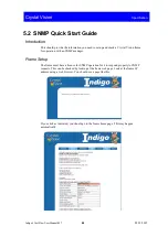
Страница 45: ...anager Frame Setup The frame must have a licence for SNMP operation for it to respond properly to SNMP requests This can be checked by looking at the frame web page Look at the frame IP address using a web browser You should see a page like this If you click as indicated you should go to the frame home page This may happen automatically Indigo 4 CoolFlow User Manual R1 7 44 03 12 2012 ...

Страница 46: ...o be changed Click and drag to select the trapsink IP address and type in the IP address of the SNMP manager being used as the trap receiver Then click on the Store button to write the new value into the frame This will take a few seconds You will then need to re boot the frame as described in the Resetting the Frame below for the setting to take effect Checking The frame should now be ready for S...

Страница 47: ...is then the frame may need to be reset to activate the SNMP licence The frame will report the presence of the licence even if it has not been activated by a reset The same walk of an unlicensed frame gives the results below Indigo 4 CoolFlow User Manual R1 7 46 03 12 2012 ...

Страница 48: ...rt the frame Note If the frame has been set to DHCP it may come back at a different IP address The frame should now be set up to respond to SNMP requests and send traps to the desired IP address Sending traps to multiple addresses To send traps to multiple addresses define multiple trapsinks in the config file Indigo 4 CoolFlow User Manual R1 7 47 03 12 2012 ...

Страница 49: ... g GPI or RS422 RS232 Contact open closure for any power supply or frame fault condition supply out of range or failure fan too slow or fail over heat RS485 loop system for front panel to all modules and rear connection rear connection by way of 26 pin high density D Type connector and RJ45 connector For shared control frame address selectable on front panel for first or second frame in a pair Sec...

Отзывы: