13
English
•
When performing works over the machine, make
sure that red-hot objects or metal chips do not fall on it
and welding cables�
•
Be cautious when executing works on capacities
or pipelines in which combustible or toxic substances
were stored� Perform their decontamination before the
beginning of work; evaporations of substances inside
capacities or pipelines can cause explosion, explosion
or poisoning�
•
Never execute works on the capacities which are
under pressure�
•
Do not use the machine for defrosting frozen pipes�
•
When working heights, observe safety procedure for
working heights�
After finishing operations
•
Having completed the work, close the compressor
outlet valve and switch it off�
•
After the final shut-off, examine a place where cut
-
ting works were carried out, do not leave decaying
subjects, or the heated particles of metal - they can
cause a fire.
•
After finishing operation do not switch off the ma
-
chine at once, wait several minutes for the machine to
cool down sufficiently.
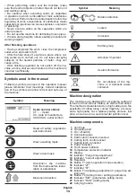
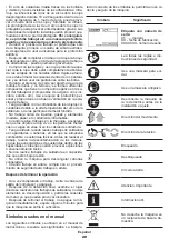
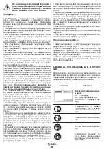
Symbols used in the manual
Following symbols are used in the operation manual,
please remember their meanings� Correct interpreta-
tion of the symbols will allow correct and safe use of
the machine�
Symbol
Meaning
Serial number sticker:
CT ��� - model;
XX - date of manufacture;
XXXXXXX - serial number�
Read all safety regulations
and instructions�
Wear a welding mask�
Wear a dust mask�
Disconnect the machine
from the mains before instal-
lation or adjustment�
Movement direction�
Symbol
Meaning
Rotation direction�
Locked�
Unlocked�
Earthing loop�
Attention� Important�
Useful information�
Do not dispose of the ma-
chine in a domestic waste
container�
Machine designation
The machines are designed for air plasma cutting of
ferrous and non-ferrous metals, as well as their alloys�
This method is characterized by a high cutting rate, the
possibility of cutting along curved trajectory, accuracy
and a high quality cut, a relatively safety process, low
price, as well as a low environmental pollution level�
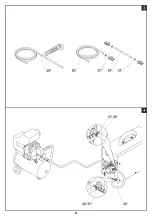
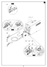
Machine components
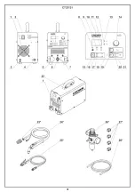
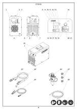
1
Vent hole
2
Grounding bolt
3
On / off switch
4
Connecting pipe
5
Earth cable connection socket
6
Cutting torch control socket
7
Cutting torch connector
8
Power indicator
9
Torch power indicator
10
Temperature protection indicator
11
Display
12
Indicator "Purge time adjustment"
13
Indicator "Current adjustment"
14
Regulator
15
Button F1 (torch operation mode selection)
16
Indicator "2T"
17
Indicator "4T"
18
Button F3 (amperage adjustment / purge time ad-
justment)
19
Button F2 (cutting mode / setting parameters)
20
Indicator "SET" (parameters setting mode)
21
Indicator "RUN" (cutting mode)
22
Carrying handle
Содержание CT33131
Страница 1: ......
Страница 3: ...3 ...
Страница 4: ...4 ...
Страница 5: ...5 ...
Страница 6: ...6 ...
Страница 7: ...7 ...
Страница 8: ...8 ...
Страница 9: ...9 ...
Страница 49: ...49 ...
Страница 50: ...50 ...
Страница 51: ...51 ...
Страница 52: ...52 ...
Страница 53: ...53 ...
Страница 54: ...54 ...
Страница 55: ...55 ...
Страница 56: ...56 ...
Страница 57: ...57 ...
Страница 58: ...58 ...
Страница 59: ...59 ...
Страница 60: ...60 ...
Страница 61: ...61 ...
Страница 62: ...62 ...
Страница 63: ...63 ...
Страница 64: ......


