


Page 7
Contractor Series Power Amplifiers
Reference Manual
ILLUSTRATIONS
Contractor Series ............................................................................................................ 1
This page intentionally left blank ..................................................................................... 2
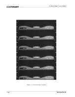
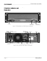
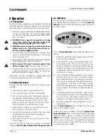
Figure 1.1 Contractor Series Amplifiers ........................................................................... 8
Figure 2.1 Contractor Series Front Panel Controls and Indicators ................................. 10
Figure 2.2 CH1 & CH2 Back Panel Controls and Connectors ....................................... 10
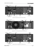
Figure 2.3 CH4 Back Panel Controls and Connectors ................................................... 11
Figure 2.4 CL1 & CL2 Back Panel Controls and Connectors ......................................... 11
Figure 2.5 CL4 Back Panel Controls and Connectors .................................................... 11
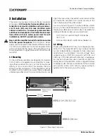
Figure 3.1 Mounting Dimensions ................................................................................... 12
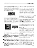
Figure 3.2 Stereo/Bridge Switch .................................................................................... 13
Figure 3.3 4/8 ohm, 70V/100V Operation Switches ........................................................ 13
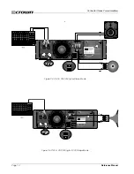
Figure 3.4 CH1 & CH2 Wiring for Stereo Mode .............................................................. 14
Figure 3.5 CH1 & CH2 Wiring for Bridge Mode ............................................................. 14
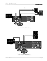
Figure 3.6 CH4 Wiring for Stereo Mode ......................................................................... 15
Figure 3.7 CH4 Wiring for Bridge Mode ........................................................................ 15
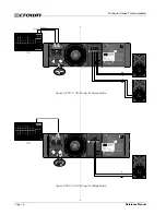
Figure 3.8 CL1 & CL2 Wiring for Stereo Mode ............................................................... 16
Figure 3.9 CL1 & CL2 Wiring for Bridge Mode .............................................................. 16
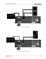
Figure 3.10 CL4 Wiring for Stereo Mode ....................................................................... 17
Figure 3.11 CL4 Wiring for Bridge Mode ....................................................................... 17
Figure. 4.1 Indicators .................................................................................................... 18
Figure 5.1 SST-MX Crossover Block Diagram ................................................................ 20
Figure 5.2 SST-SX Crossover Block Diagram ................................................................. 21
Figure 5.3 SST-SBSC Crossover Block Diagram ............................................................ 21
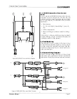
Figure 6.1 CH1 & CH2 Circuit Block Diagram ............................................................... 22
Figure 6.2 CL1 & CL2 Circuit Block Diagram ................................................................ 23
Figure 6.3 CH4 Circuit Block Diagram ........................................................................... 24
Figure 6.4 CL4 Circuit Block Diagram ........................................................................... 25
Figure 7.1 Contractor Series Output Power ................................................................... 29
Figure 7.2 CH1 & CH2 Frequency Response ................................................................ 29
Figure 7.3 CL1 & CL2 Frequency Response ................................................................. 29
Figure 7.4 CH4 & CL4 Frequency Response ................................................................. 30
Figure 7.5 CH1, CH2, CL1 & CL2 Damping Factor ....................................................... 30
Figure 7.6 CH4 & CL4 Damping Factor ......................................................................... 30
Figure 7.7 CH1, CH2, CL1 & CL2 Output Impedance ................................................... 31
Figure 7.8 CH4 & CL4 Output Impedance .................................................................... 31
Figure 8.1 CH1 Power Draw, Current Draw and Thermal Dissipation ............................. 32
Figure 8.2 CH2 Power Draw, Current Draw and Thermal Dissipation ............................. 33
Figure 8.3 CH4 Power Draw, Current Draw and Thermal Dissipation ............................. 33
Figure 8.4 CL1 Power Draw, Current Draw and Thermal Dissipation ............................. 33
Figure 8.5 CL2 Power Draw, Current Draw and Thermal Dissipation ............................. 34
Figure 8.6 CL4 Power Draw, Current Draw and Thermal Dissipation ............................. 34
Figure 9.1 Extra Cooling with a Rack-Mounted Blower .................................................. 35
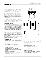
Figure 9.2 Balanced & Unbalanced Input Wiring .......................................................... 36
Figure 9.3 Polarity Conversions ..................................................................................... 36
Figure 9.4 Balanced Input Wiring ................................................................................ 36
Figure 9.5 Unbalanced Input Wiring ............................................................................ 36
Figure 9.6 Infrasonic Filter Capacitor Values ................................................................ 37
Figure 9.7 Unbalanced RFI Filters ................................................................................. 37
Figure 9.8 Balanced RFI Filters .................................................................................... 37
Figure 9.9 Wire Size Nomograph .................................................................................. 38
Figure 9.10 Inductive Load (Transformer) Network ........................................................ 39
Figure 9.11 Loudspeaker Fuse Nomograph .................................................................. 40
Figure 9.12 Fault Status LED Circuitry ........................................................................... 40
Figure 9.13 RJ Jack Wiring and Pin Assignments ......................................................... 40
Figure 10.1 Restaurant System Example ....................................................................... 41
Figure 10.2 House of Worship System Example ............................................................ 42


