


Page 40
Contractor Series Power Amplifiers
Reference Manual
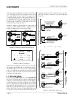
9.5 Fault Circuit Wiring
To set up a circuit that will cause an LED to light when-
ever a fault status occurs, you can simply use the sug-
gested circuit shown in Figure 9.12.
Figure 9.12 Fault Status LED Circuitry
When using this circuit, the LED will glow whenever the
amplifier is in one of four states: a channel’s heatsink
has reached its temperature limit, the transformer has
reached its temperature limit, the amplifier has just been
turned on and is in its turn-on-delay mode, or the ampli-
fier is turned off.
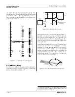
If you choose to design your own circuit to interface this
signal to your system, note that this RJ jack is polarity-
sensitive. Pin 2 must be grounded, and Pin 5 must be
supplied with a positive voltage pull up (positive with
respect to ground). Refer to Figure 9.13 for RJ jack pin
assignments.* The maximum signal that can be ex-
posed to the fault jack is 35 VDC and 10 mA. Best re-
sults are obtained with 10 mA LEDs.
Figure 9.13 RJ Jack Wiring and Pin Assignments
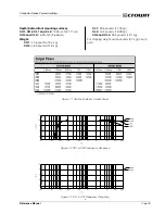
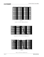
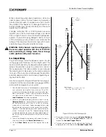
Figure 9.11 Loudspeaker Fuse Nomograph
1.0
1.2
1.4
1.6
2.5
3
4
5
6
7
8
9
10
12
14
16
20
25
30
20
15
10
8
6
5
4
3
2
1.5
1
.8
.6
.5
.4
.3
.2
.15
.1
.08
3000
2000
1500
1000
800
600
400
300
200
150
100
80
60
40
30
20
15
10
8
6
4
3
2
1.5
1
SPEAKER Z
(ohms)
FUSE
(amps)
SPEAKER RATING
PEAK MUSIC POWER
(watts)
(Typically 4 times the continuous average power)
Example: Z = 8 ohms.
Peak Power = 75 W
Answer: Fuse = 1.5 A
2
40
* The mating connector for the RJ11 Fault jack contains 4 contact pins in
a 6-slot case, as shown. For additional information please contact your
local dealer or Crown Technical Support.
are usually damaged by large transient voltages. This
means that your loudspeakers will tend to have better
protection when the woofers are protected by slow-blow
fuses and high-frequency drivers are protected by high-
speed instrument fuses.


