background image

MIN

AR

Y

PRELIMINAR

Y

MIN

AR

Y

MIN

AR

Y

MINA

PRELIM

INA

MIN

AR

Y

PRELIMINAR

Y

PRELIMINAR

Y

PRELI

MIN

LIM

INAR

Y

LIMIN

PREL

IM

PREL

IM

PRELIMINAR

Y

PRELI

MIN

130808-1

5/00

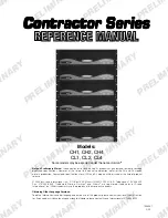
Models:

CH1, CH2, CH4

CL1, CL2, CL4

Some models may be exported under the name 

Amcron.

®

Con

Con

Con

Con

Contr

tr

tr

tr

tractor Series

actor Series

actor Series

actor Series

actor Series

Note on Preliminary Status:

 Crown continues to stand behind its products as guaranteed to meet or exceed

published specifications. However, at the time of this manual’s publication, not all of the CH and CL models
were in production. Guaranteed specifications for all CH and CL models will be issued at the time of product
release.

© 2000 by Crown International, Inc., P.O. Box 1000, Elkhart, IN 46515-1000 U.S.A. Telephone: 219-294-8000.
Fax: 219-294-8329. Trademark Notice: 

Amcron

®

  and Crown

®

 are registered trademarks of Crown

International, Inc. Other trademarks are the property of their respective owners.

Obtaining Other Language Versions:

To obtain information in another language about the use of this product, please contact your local Crown Distribu-

tor. If you need assistance locating your local distributor, please contact Crown International at 219-294-8200.

Содержание CH1

Страница 1: ...al s publication not all of the CH and CL models were in production Guaranteed specifications for all CH and CL models will be issued at the time of product release 2000 by Crown International Inc P O Box 1000 Elkhart IN 46515 1000 U S A Telephone 219 294 8000 Fax 219 294 8329 Trademark Notice Amcron and Crown are registered trademarks of Crown International Inc Other trademarks are the property o...

Страница 2: ...Page 2 Contractor Series Power Amplifiers Reference Manual This page intentionally left blank ...

Страница 3: ... electrician for replacement of the obsolete outlet 10 Protect the power cord from being walked on or pinched particularly at plugs convenience recep tacles and the point where they exit from the appara tus 11 Only use attachments accessories specified by the manufacturer 12 Use only with a cart stand bracket or table speci fied by the manufacturer or sold with the apparatus When a cart is used us...

Страница 4: ...eriodofthree 3 yearsfromthedateofpurchasebytheoriginalpurchaser the warrantyperiod thatthenewCrownproductisfreeofdefectsinmaterials and workmanship We further warrant the new Crown product regardless of the reason for failure except as excluded in this Warranty ITEMS EXCLUDED FROM THIS CROWN WARRANTY This Crown Warranty is in effect only for failure of a new Crown product which occurred within the...

Страница 5: ... does it cover every possible situation which may arise during installation operation or mainte nance If your unit bears the name Amcron please substitute it for the name Crown in this manual If you need special assistance beyond the scope of this manual please contact our Technical Support Group Crown Audio Technical Support Group Plant 2 SW 1718 W Mishawaka Rd Elkhart Indiana 46517 U S A Phone 8...

Страница 6: ...ssover 20 5 3 3 SST SBSC Module 21 5 4 Fault Monitoring 21 5 5 Constant Voltage Computer 21 6 Principles of Operation 22 6 1 CH1 CH2 CL1 and CL2 22 6 2 CH4 and CL4 24 6 2 1 Audio Signal Path 24 6 2 2 Power Supply Operation 26 7 Specifications 27 8 AC Power Draw and Thermal Dissipation 32 9 Installation Helps 35 9 1 Cooling 35 9 1 1 Additional Cooling 35 9 2 Input Wiring 35 9 2 1 Solving Input Prob...

Страница 7: ... 24 Figure 6 4 CL4 Circuit Block Diagram 25 Figure 7 1 Contractor Series Output Power 29 Figure 7 2 CH1 CH2 Frequency Response 29 Figure 7 3 CL1 CL2 Frequency Response 29 Figure 7 4 CH4 CL4 Frequency Response 30 Figure 7 5 CH1 CH2 CL1 CL2 Damping Factor 30 Figure 7 6 CH4 CL4 Damping Factor 30 Figure 7 7 CH1 CH2 CL1 CL2 Output Impedance 31 Figure 7 8 CH4 CL4 Output Impedance 31 Figure 8 1 CH1 Power...

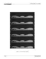
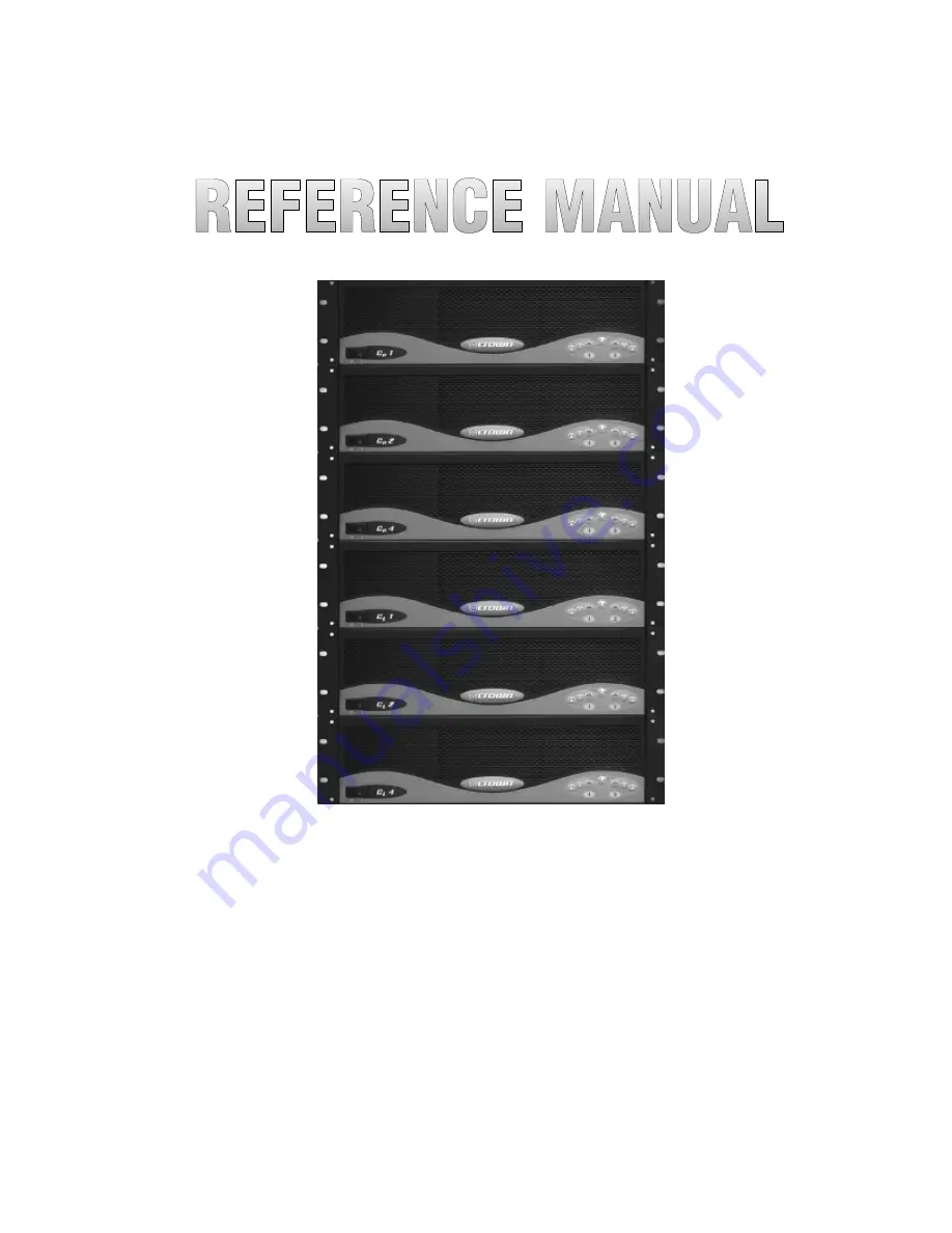
Страница 8: ...Page 8 Contractor Series Power Amplifiers Reference Manual Figure 1 1 Contractor Series Amplifiers ...

Страница 9: ...by each channel CH Series includes a 70 Hz high pass filter for each channel when used in 70V or 100V mode providing necessary low frequency roll off to eliminate saturation of constant voltage step down transformers typically used in 70V and 100V distributed systems CL Series includes high power 2 ohm operation for jobs where low impedence is the only requirement A green Signal LED for each chann...

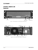
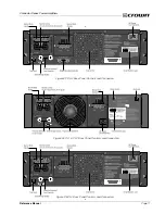
Страница 10: ... Contractor Series Power Amplifiers Reference Manual Figure 2 1 Contractor Series Front Panel Controls and Indicators 2 Controls Indicators and Connectors Figure 2 2 CH1 CH2 Back Panel Controls and Connectors ...

Страница 11: ...1 Contractor Series Power Amplifiers Reference Manual Figure 2 3 CH4 Back Panel Controls and Connectors Figure 2 4 CL1 CL2 Back Panel Controls and Connectors Figure 2 5 CL4 Back Panel Controls and Connectors ...

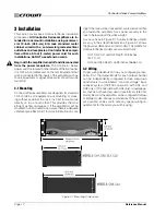
Страница 12: ...des the most efficient air flow and support If the amplifier s will be mounted in an enclosed rack assure there is adequate ventilation see Section 9 1 for more information on cool Figure 3 1 Mounting Dimensions ing If the rack will be transported we recommend that you fasten the amplifier s back panel securely to the rack to help support the unit s weight As you can see in Figure 3 1 Contractor S...

Страница 13: ...eating and premature activation of the pro tection circuitry Note The Channel 2 input jack and Input Level control are not defeated in Bridge mode A signal feeding Channel 2 will work against the Channel 1 signal and usually results in distortion and inefficient operation 3 2 1 Input Wiring The balanced inputs have a nominal impedance of 20 k ohms 10 k ohms unbalanced and will accept the line leve...

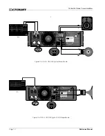
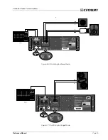
Страница 14: ...Page 14 Contractor Series Power Amplifiers Reference Manual Figure 3 4 CH1 CH2 Wiring for Stereo Mode Figure 3 5 CH1 CH2 Wiring for 140V Bridge Mode ...

Страница 15: ...Page 15 Contractor Series Power Amplifiers Reference Manual Figure 3 6 CH4 Wiring for Stereo Mode Figure 3 7 CH4 Wiring for Bridge Mode ...

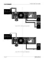
Страница 16: ...Page 16 Contractor Series Power Amplifiers Reference Manual Figure 3 8 CL1 CL2 Wiring for Stereo Mode Figure 3 9 CL1 CL2 Wiring for Bridge Mode ...

Страница 17: ...Page 17 Contractor Series Power Amplifiers Reference Manual Figure 3 10 CL4 Wiring for Stereo Mode Figure 3 11 CL4 Wiring for Bridge Mode ...

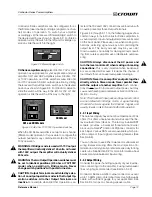
Страница 18: ...dio source to the desired level 5 Turn up the Input Level controls on the back panel of the amplifier until the desired loudness or power level is achieved 6 Turn down the level of your audio source to its normal range If you ever need to make any wiring or installation changes don t forget to disconnect the power cord 4 3 Indicators The front panel of a Contractor Series amplifier has sev eral he...

Страница 19: ... Options section Section 5 of this manual for more information on fault monitoring and suggestions for signalling device circuity A circuit breaker is provided to prevent the high voltage power supplies from drawing excessive current A Re set switch for the circuit breaker is provided on the back panel If the circuit breaker trips the Power indicator turns off In this situation turn off the Power ...

Страница 20: ...an optional Crown SST crossover module please refer to the applicable SST Crossover Reference Manual Refer to the following descriptions for an overview of available Crown SST crossover modules 5 3 1 SST MX Crossover The SST MX crossover module features 24 dB octave Linkwitz Riley tuned filters and stereo sub bass outputs for biamp operation of subs See Figure 5 1 for SST MX block diagram Features...

Страница 21: ... to release additional accessory plug in modules offering a range of advanced features and capabilities Watch for new releases 5 4 Fault Monitoring The Fault RJ11 jack is located on the back of your Contractor Series amplifier It gives you an easy way to remotely monitor the amplifier s fault status See Sec tion 9 5 for details about how to connect external cir cuits to the Fault jack 5 5 Constant...

Страница 22: ... in the signal path The signal then travels either through the HP filter mod ule or is bypassed around it depending on the position of the channel operation switch In the CH1 and CH2 with the switch set in the 70V 100V position the filter is enabled The filter is an 18 dB per octave high pass with a 3 dB rolloff at 70 Hz This provides a measure of protection to step down transformers used in distr...

Страница 23: ... the fan Should the power transformer reach its maximum safe temperature an internal thermal switch opens and the fan circuit turns on full speed to quickly cool down the amplifier It also disconnects the load via the output relay removing any output current and further speeding a cool down cycle This point is set both to protect speakers and to guard against nuisance tripping Whenever the heatsin...

Страница 24: ... the modulator stage and the output filter both described below from receiv ing signals that are too high Without the 32 kHz filter the modulator would be unable to process signals that are too high and the output filter would not yield the proper frequency response behavior The Gaussian fil ter type is unique in that it has minimal ringing and ex cellent phase response so even a high order filter...

Страница 25: ...lat meaning that regardless of the output voltage the output current always limits at a certain value The turn on delay circuitry functions to keep the modu lators turned off which keeps the outputs from switch ing until all supplies are up and stable Thermal probes monitor Heatsink temperatures and power transformer temperature As the temperatures rise the probes send a proportional voltage to th...

Страница 26: ...s The circuit also uses intelligence to draw the current from the line sinusoidally and in phase with the line voltage This reduces the load on the power companies and also allows the amplifier to pull more peak power from the power source the outlet The power is drawn in small amounts 62 500 times each second and is used to provide power to the isolation stage and to fill the large energy reservo...

Страница 27: ...at 4 8 ohm CL2 32 1 dB at 4 8 ohm CL4 34 dB 4 8 ohm AC Line Requirements Note North American CH 1 CL 1 CH 2 and CL 2 units are 60 Hz only All other models are 50 60 Hz Voltages are 10 AC Line Current CH 1 CL 1 100 Volts 7 6 A 120 Volts 6 3 A 230 240 Volts 3 5 A CH 2 CL 2 100 Volts 11 4 A 120 Volts 9 5 A 230 240 Volts 5 0 A CH 4 CL 4 100 Volts 8 5 A 120 Volts 7 1 A 230 240 Volts 3 7 A AC Line Conne...

Страница 28: ... Neutrik Combo connector for each channel which features a balanced inch 6 35 mm phone jack and a 3 pin female XLR connector in parallel with a barrier strip termination Input Stage Input is electronically balanced and employs precision 1 resistors Input Impedance Nominally 20 k ohms balanced Nominally 10 k ohms unbalanced Input Sensitivity Channel independent Factory set at 1 4 volts for standard...

Страница 29: ... 4 and CL 4 16 25 inch 36 56 cm Weight CH 1 40 6 pounds 18 4 kg CH 2 48 3 pounds 21 9 kg Figure 7 1 Contractor Series Output Power Figure 7 2 CH1 CH2 Frequency Response Figure 7 3 CL1 CL2 Frequency Response CL 1 32 6 pounds 14 78 kg CL 2 40 3 pounds 18 28 kg CH 4 and CL 4 33 3 pounds 15 1 kg For shipping weight add 6 pounds 2 7 kg to each amp ...

Страница 30: ...Page 30 Contractor Series Power Amplifiers Reference Manual Figure 7 4 CH4 CL4 Frequency Response Figure 7 5 CH1 CH2 CL1 CL2 Damping Factor Figure 7 6 CH4 CL4 Damping Factor ...

Страница 31: ...Page 31 Contractor Series Power Amplifiers Reference Manual Figure 7 7 CH1 CH2 CL1 CL2 Output Impedance Figure 7 8 CH4 CL4 Output Impedance ...

Страница 32: ...0 Duty cycle of highly compressed rock n roll midrange is 40 Duty cycle of rock n roll is 30 Duty cycle of background music is 20 Duty cycle of continuous speech is 10 Duty cycle of infrequent paging is 1 Here are the equations used to calculate the data pre sented in Figures 8 1 through 8 6 The value used for Amplifier Efficiency is 0 65 for CH1 CH2 CL1 and CL2 models and 0 77 for CH4 and CL4 mod...

Страница 33: ...l Figure 8 2 CH2 Power Draw Current Draw and Thermal Dissipation at Various Duty Cycles Figure 8 3 CH4 Power Draw Current Draw and Thermal Dissipation at Various Duty Cycles Figure 8 4 CL1 Power Draw Current Draw and Thermal Dissipation at Various Duty Cycles ...

Страница 34: ...tor Series Power Amplifiers Reference Manual Figure 8 5 CL2 Power Draw Current Draw and Thermal Dissipation at Various Duty Cycles Figure 8 6 CL4 Power Draw Current Draw and Thermal Dissipation at Various Duty Cycles ...

Страница 35: ...for higher power output is usually used at higher average output levels So for example a CL2 delivering full output will require more air flow than a CL1 9 1 1 Additional Cooling If multiple amplifiers will be operated under demanding conditions such as driving loads less than 4 ohms or if air flow through the rack will be restricted you should verify that the total air flow through the rack will ...

Страница 36: ...citor in series with the input signal line The graph one leg at ground potential while the second leg is hot Unbalanced line is less expensive but is much more susceptible to noise and is not usually used in professional applications For the cleanest signal with out unwanted hum and buzz balanced line is always recommended It is especially helpful if you have a long cable run over 10 feet 3 m sinc...

Страница 37: ...m the bias signal of many tape recorders To prevent high levels of input RF install an appropriate low pass filter in series with the input signal Some examples of unbalanced wiring for low pass filters are shown in Figure 9 7 Balanced In 910 Ω 003 f µ 015 f µ 018 f µ 1 8 mH 2 5 mH A C B 015 f µ 1 8 mH D Balanced Out 910 Ω 1 8 mH 2 5 mH 1 8 mH Balanced In Balanced Out Balanced In Balanced Out Bala...

Страница 38: ...of the amplifier If you are using 70V or 100V output be sure to determine the load resistance of the step down transformers Crown s constant voltage computer can help with this see Section 5 5 Mark this value on the Load Resistance line of the nomograph 2 Select an acceptable damping factor and mark it on the Damping Factor line Your amplifier can provide an excel lent damping factor of 400 from 1...

Страница 39: ...al path at the input when in 70V or 100V mode If driving an inductive load either with a CH Series amplifier in 4 8 ohm mode or with a CL Series amplifier always take the precaution of installing a high pass filter in series with the amplifier s input An 18 dB per octave filter between 50 and 70 Hz is recommended Another way to protect inductive loads from large low frequency currents and prevent ...

Страница 40: ...igure 9 13 for RJ jack pin assignments The maximum signal that can be ex posed to the fault jack is 35 VDC and 10 mA Best re sults are obtained with 10 mA LEDs Figure 9 13 RJ Jack Wiring and Pin Assignments Figure 9 11 Loudspeaker Fuse Nomograph 1 0 1 2 1 4 1 6 2 5 3 4 5 6 7 8 9 10 12 14 16 20 25 30 20 15 10 8 6 5 4 3 2 1 5 1 8 6 5 4 3 2 15 1 08 3000 2000 1500 1000 800 600 400 300 200 150 100 80 6...

Страница 41: ...elatively long speaker lines without significant line loss are possible due to the high voltage low current characteristics of the 70V distributed method Taking advantage of the flexible output options with the CH Series amplifiers Channel 2 is set to 4 8 ohm operation to drive full range speakers in the Bar For the dance floor a CL2 is used in Stereo mode with each channel driving two full range ...

Страница 42: ...are possible due to the high voltage low current characteristics of the 70V distributed method The CL2 is used in Stereo mode One channel will drive multiple delay speakers in a balcony The other channel will drive multiple stage monitors The low impedance capability of the CL Series allow multiple speakers to be paralled on each channel The CL4 is chosen because of its high power capabil ity and ...

Страница 43: ...ground shipping both ways in the United States Contact Crown Factory Service or Technical Support to obtain prepaid ship ping labels prior to sending the unit Or if you prefer you may prepay the cost of shipping and Crown will reimburse you Send copies of the shipping receipts to Crown to receive reimbursement Your repaired unit will be returned via UPS ground Please contact us if other arrangemen...

Страница 44: ..._________________ ______________________________________________________________________________ ______________________________________________________________________________ ______________________________________________________________________________ ______________________________________________________________________________ __________________________________________________________________...

Отзывы: