background image


TABLE 2.1 IN

NPUT AND OUTPUT SIGNALS

TABLE 2.1 INPUT AND OUTPUT SIGNALS

TABLE 2.1 IN

PUT AND OUTPUT SIGNALS

CONNECTOR

GENERAL FUNCTION 2099  FUNCTION

COMMENTS

J1

10 MHz INPUT

0.5 TO 1.5 V P-P (-4 to +6 dBm into 75 ohms)

J2

DC IN

± 15 VDC, 3PIN MINI-DIN

J3

PCB EDGE CONNECTOR

INTERNAL USE

J4 - PIN

1

GROUND

2

75

 or 2 K

, 10MHz Signal In

Impedance electable by jumper JP1 on rear panel)

3

NOT  USED

4

RS422 Clock A Out (+)

One end of RS422 Clock A output

5

RS422 Clock A Out (-)

One end of RS422 Clock A output

6

NOT  USED

7

NOT  USED

8

+15 VDC Backup In 

180 ma max,

9

+15 VOLTS.

180 ma max, from J2 Main Power Supply

10

MAJOR Alarm relay output

Open or short (selectable) to pin 12 if PLL alarm or no 10 MH

11

-15 VOLTS

60 ma max, from J2 Main Power Supply

12

MAJOR Alarm relay output

Open or short (selectable) to pin 10 if PLL alarm or no 10 MH

13

NOT USED

14

-15 VDC Backup In

60 ma max

15

MANUAL ALARM OPEN COLLECTOR 

Shorts to ground (+30 VDC,100 ma max) if S1 not in AUTO

16

RS422 Clock B OUT (+)

One end of RS422 Clock B output

17

RS422 Clock B OUT (-)

One end of RS422 Clock B output

18

GROUND

TABLE 2.1 2099-42 Inputs and Outputs

2099-42 manual Rev. A

Page 8

10/27/2005

Содержание 2099-42

Страница 1: ...oses of operating the equipment When ordering parts from Cross Technologies Inc be sure to include the equipment model number equipment serial number and a description of the part First Edition Octobe...

Страница 2: ...rials and workmanship for a period of one year after shipment to customer Cross Technologies Inc s obligation under this warranty is limited to repairing or at Cross Technologies Inc s option replacin...

Страница 3: ...manually selects internal or external lock to 10 MHz control of the VCXO Diodes on the DC inputs allow operation from redundant power supplies An open collector indicates Manual operation and relay c...

Страница 4: ...or AUTO select Int Freq Adjusts frequency of internal VCXO when not locked to external 10 MHz INT EXT LED LED lights RED if VCXO controlled internally Green if locked to external 10 MHz MAN LED LED li...

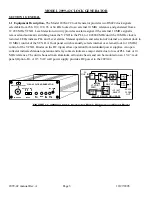
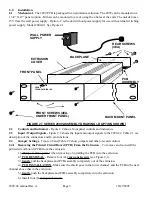
Страница 5: ...nput Output Signals Figure 2 3 shows the input and output signals to the 2099 42 Table 2 1 is a description of the connectors and J4 pin functions 2 4 Jumper Settings Figure 2 4 and Table 2 2 show jum...

Страница 6: ...moved the PLL will lose lock and will force the internal VCXO to have the frequency set by front panel potentiometer R20 R20 DOES control the VCXO in this mode if it has automatically switched to Inte...

Страница 7: ...ll light occasionally depending on how far off in frequency the VCXO is set from locking to it DS3 EXTERNAL REFERENCE PRESENT LED Lights GREEN when 10 MHz external reference is present and RED if belo...

Страница 8: ...RS422 Clock A output 6 NOT USED 7 NOT USED 8 15 VDC Backup In 180 ma max 9 15 VOLTS 180 ma max from J2 Main Power Supply 10 MAJOR Alarm relay output Open or short selectable to pin 12 if PLL alarm or...

Страница 9: ...EQUENCY N A N A N A JUMPER POSITION SELECTS 64 TO 256 CLOCK FREQUENCY CH A JP5 CLOCK A FREQUENCY N A N A N A JUMPER POSITION SELECTS 64 TO 256 CLOCK FREQUENCY CH B TABLE 2 2 JUMPER DESCRIPTIONS K1 R20...

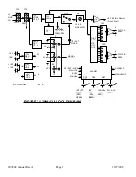
Страница 10: ...and clock B RS422 outputs The external 10 MHz reference frequency also goes to buffer amplifier U7 which drives peak detector CR8 and then goes to op amp U8 the output of which provides a 5 signal if...

Страница 11: ...T MANUAL ALARM UP U3 INT EXT CLOCK PIN 2 PIN 3 VCXO INT FREQ R20 12 288 MHZ VCXO 5V REG VR3 15 A 15B 15 A 15B 12 12 5 12V REG VR1 12V REG VR2 U10 U5 U6 Q2 256 128 64 192 96 INT EXT CLOCK RED GREEN REF...

Отзывы: