2.2
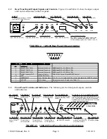
Rear Panel Input/Output Signals and Controls - Figure 2.2 and Table 2.1 show the input, output.
and control connectors on the rear panel.
J102 - FDM TX IN
Input, BNC female, 50
Ω
.
J101 - DIG1 TX IN
Input, BNC female, 50
Ω
.
J103 - DIG2 TX IN
Input, BNC female, 50
Ω
.
J104 - TX IF OUT
Output, BNC female, 50
Ω
.
J105 - SWITCH CONTROL
DB9, female. Allows for REMOTE control of the
1200-05 TX switches, and contains AGC and
LOCAL indicator signals. See Tables 2.1 and 2.2.
AC
GND
J107
DIG1
RX OUT
J106
J105
J108
J109
FDM
RX OUT
DIG2
RX OUT
RX
IF IN
CONTROL
J102
DIG1
TX IN
J101
J103
J104
FDM
TX IN
DIG2
TX IN
TX
IF OUT
J107 - FDM RX OUT
Output, BNC female, 50
Ω
.
J106 - DIG1 RX OUT
Output, BNC female, 50
Ω
.
J108 - DIG2 RX OUT
Output, BNC female, 50
Ω
.
J109 - RX IF IN
Input, BNC female, 50
Ω
.
AC INPUT
AC input for power supply. 100-240
±10% VAC, 47-63 Hz, 30W max.
FIGURE 2.2 1200-05 Rear Panel I/Os and Control
5
1
2
3
4
6
7
8
9
TABLE 2.1 -
2.1
- J105 (DB9) Control//Indicator
Control
/Indicator Signals
PIN
CONTROLS
1
SELECT DIG1 TX IN
External Closure In
GND/Open OFF; +15 VDC(+V) ON
2
SELECT FDM TX IN
External Closure In
GND/Open OFF; +15 VDC(+V) ON
3
SELECT DIG2 TX IN
External Closure In
GND/Open OFF; +15 VDC(+V) ON
4
LOCAL Indicator OUT
Indicator Output
GND LOCAL Control; Open REMOTE Control
5 9
GND
Ground Reference
6
OVERRIDE IN
Local Override Input
+15 VDC (+V) overrides LOCAL control and allows for REMOTE control
7
AGC OUT
AGC Voltage
Indicates current AGC gain (see Table 2.2)
8
+V
DC Voltage Ref15 VDC
2.3
Front Panel Controls and Indicators - The following are the front panel outputs, controls
and indicators.
J1 - RX IF MON
RX monitor output
after AGC, BNC
female.
MODEL 1200
IF PROCESSOR
DC
OVERRIDE
LOCAL
DIG2
FDM
DIG1
SW1
SW2
SW3
SW4
LOCAL
REMOTE
ON
ON
ON
TX
IF MON
RX
IF MON
J1
J2
GAIN
T3
R1
R2
R3
T1
T2
DIG1
FDM
DIG2
DS1 - DIG1 LED
Lights green when
DIG1 TX is on.
DS2 - FDM LED
Lights green when
FDM TX is on.
DS3 - DIG2 LED
Lights green when
DIG2 TX is on.
SW1 - DIG1 TX SW
Turns on (up) DIG1
TX input when in
LOCAL operation.
J2 - TX IF MON
TX monitor output of the
switched (combined) TX
output, BNC female.
SW2 - FDM TX SW
Turns on (up) FDM
TX input when in
LOCAL operation.
SW3 - DIG2 TX SW
Turns on (up) DIG2
TX input when in
LOCAL operation.
SW4 - LOCAL/REMOTE SW
Switches between LOCAL
and REMOTE operation.
DS4 - LOCAL LED
Lights red when in
LOCAL operation.
DS5 - OVERRIDE LED
Lights yellow when REMOTE
control is overriding LOCAL
control.
R1, R2, R3, T1, T2, T3 - ADJUSTABLE ATTEN
Potentiometers that control the attenuation of RX
DIG1 (R1), RX FDM (R2), RX DIG2 (R3), TX DIG1
(T1), TX FDM (T2), and TX DIG2 (T3) channels.
Adjustable from 0 to 30 dB attenuation. Clockwise
rotation decreases attenuation.
DS6 - POWER LED
Lights green when
DC power is applied.
FIGURE 2.3 1200-05 Front Panel Controls and Indicators
1200-05 Manual, Rev. 0
Page 6
10/14/10

