SmarTouch™ Control Processor
Crestron
ST-CP
3. Attach supplied antenna to BNC connector labeled RF on the back of
the ST-CP.
4. Insert the mono mini plug of the STIRP into one of the four IR OUT
ports of the ST-CP. Identifying the correct IR OUT port depends on the
designations made when programming. In the illustration provided, it is
assumed that the VCR is assigned to PORT A. Refer to the latest
revision of the STIRP Installation Instructions (Doc. 5674) for details
to attach the STIRP to IR sensor windows.
5. Repeat previous step, as necessary.
Problem Solving
Troubleshooting
The table below provides corrective action for possible trouble situations. If further
assistance is required, please contact a Crestron customer service representative.
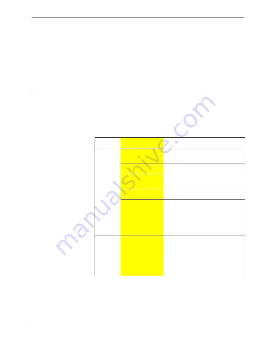
ST-CP Troubleshooting
TROUBLE
POSSIBLE
CAUSE(S)
CORRECTIVE ACTION
A/V device
does not
respond.
STIRP or serial port not
placed properly.
Verify placement of STIRP (Hold phosphor
card under STIRP while pressing button) and
tightness of serial cable.
Used wrong IR or serial
port.
Verify proper IR or serial port is defined.
Wrong manufacturer or
model number listed in
SmarTouch system.
Open the project in software and verify
device definition.
Incorrect program is in
control system.
Verify program is uploaded to control system
with Performance Viewport from the software.
Incorrect panel screens
are in touchpanel.
Use the software to open the project and
verify that each button that is suppose to
control the device has a join number and the
command associated with it lists
"SEND<device name> <function name>"
(e.g., SEND LIV_RM_VCR PLAY).
Download the touchpanel screens again.
A/V device
does not
respond and
wrong LEDs
on ST-CP for
device’s IR or
serial port
illuminate.
SmarTouch system
calls out wrong port or
no port for device.
Open SmarTouch system via software and
change the port.
8
•
SmarTouch™ Control Processor: ST-CP
Operations Guide - DOC. 5820


