

Crestron
MPS-250
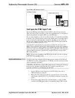
Multimedia Presentation System 250
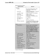
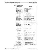
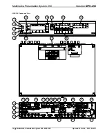
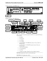
Connectors, Controls & Indicators
#
CONNECTORS
1
,
CONTROLS &
INDICATORS
DESCRIPTION
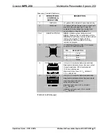
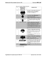
1
NET LED
(1) yellow LED, indicates Cresnet bus activity.
2
MSG LED
(1) yellow LED, illuminates when a message is
present in the message log. To view the
contents of the message log, use the front
panel buttons or Crestron Toolbox™.
3 & 4
RESET BUTTONS
HW-R
– Initiates system hardware reset.
SW-R
– Pressing this in combination with the
HW-R
button performs a system restart without
loading the program. Pressing it alone
momentarily while the system is running
restarts the program.
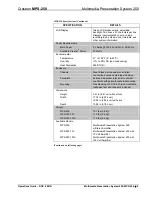
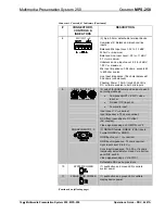
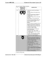
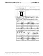
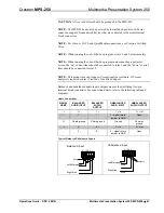
5
COMPUTER
Pin 1 Pin 2
Pin 4 Pin 3
(1) USB Type B female; USB 1.1 computer
console port (cable included)
PIN
DESCRIPTION
1
+5 VDC
2
Data -
3
Data +
4
Ground
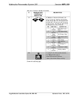
6
PROGRAM OUT (L/R)
(1) 5-pin 3.5 mm detachable terminal block;
Balanced/unbalanced stereo line-level output
Output Impedance: 200 ohms balanced,
100 ohms unbalanced
Maximum Output Level: 4 V
rms
balanced,
2 V
rms
unbalanced
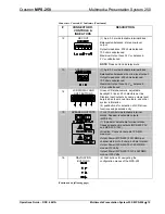
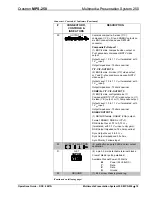
7
AUDIO INPUTS 1-5
(5) 5-pin 3.5 mm detachable terminal blocks
Balanced/unbalanced stereo line-level inputs
Input Impedance: 24k ohms
balanced/unbalanced
Balanced Input Level: -20 to +12 dBV;
4 V
rms
maximum
Unbalanced Input Level: -20 to +6 dBV;
2 V
rms
maximum
(Continued on following page)
Operations Guide – DOC. 6647A
Multimedia Presentation System 250: MPS-250
•
13
Содержание MPS-250
Страница 1: ...Crestron MPS 250 MultimediaPresentationSystem250 Operations Guide ...
Страница 4: ......


