background image

35 • GL-IPAC-SW8

Product Manual — Doc. 7389C

5. Press Set to confirm the address. The GL-IPAC-SW8 must be restarted after altering the

IP address.

NOTE: After setting the IP address of the remote control system, an EIC must be
added to the remote system program. On the EIC, joins 200-219 are dedicated for the
remote keypads.

l

Press Clear to delete the IP Address.

l

Press Exit to save the settings and return to the Rmte Keypd List screen.

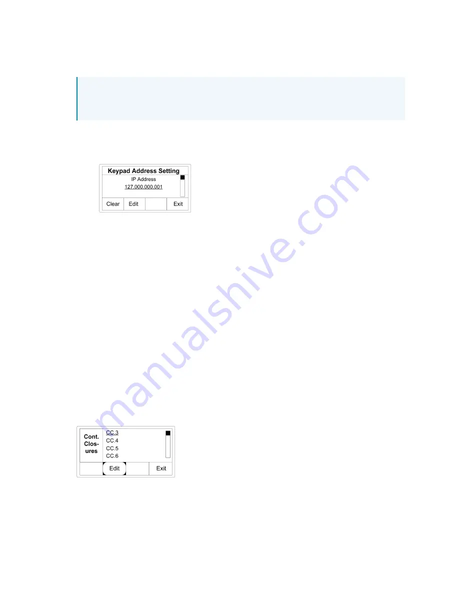
Keypad Address Setting Screen

Contact Closures

Trigger specific actions using two predefined contact closure inputs and six custom contact
closure inputs.

Select Contact Closures from the Setup menu to show a list of the six editable contact closures
(CC3 - CC.8).

l

Contact closure 1 is preprogrammed to lock the GL-IPAC-SW8.

l

Contact closure 2 preprogrammed to lock all keypads in the system.

l

Contact closures 3 -8 (CC.3 -CC.8) can be programmed using the same functions as the
keypads, in addition to being able to lock, unlock, and lock/unlock the GL-IPAC-SW8 or the
keypads.

To program the functions for the contact closures:

1. Use ▼ and ▲ to highlight a contact closure and press Edit.

Contact Closures Screen

2. Select one from the Select function screen: On, Off, Toggle, Custom, Enter Override, Exit

Override, Enter/Exit Override, Enable Timeclock, Disable Timeclock, Enable/Disable
Timeclock, Lock Keypads, Unlock Keypads, Lock/Unlock Keypads, Lock GL-IPAC-SW8,

Содержание Green Light GL-IPAC-SW8

Страница 1: ...GL IPAC SW8 Crestron Green Light Integrated Switching System Product Manual Crestron Electronics Inc ...

Страница 2: ...specific patents that cover Crestron products are listed online at patents crestron com Certain Crestron products contain open source software For specific information please visit www crestron com opensource Crestron the Crestron logo and Crestron Green Light are either trademarks or registered trademarks of Crestron Electronics Inc in the United States and or other countries UL and the UL logo a...

Страница 3: ... the Number of External Loads 23 Set External Load IDs 24 Occupancy Sensors 24 Internally Connected Occupancy Sensors 25 Cresnet Connected Occupancy Sensors 25 GLS SIM Connected Occupancy Sensors 26 Assign an Occupancy Sensor 27 Photo Sensors 29 Photo Sensor Range 29 Lighting Threshold Settings 30 Assign Photo Sensors to Loads 31 Keypads 32 Program Button Function 33 Assign Button Function and Sel...

Страница 4: ...Troubleshooting 41 iv Contents Product Manual Doc 7389C ...

Страница 5: ...v Contents Product Manual Doc 7389C ...

Страница 6: ...amming for a complete switching system consisting of up to 64 switched loads 16 local and two remote keypads 24 occupancy and photo sensors and 100 time clock events Keypads with as many as 12 buttons each can be programmed easily to control lighting loads and other functions Lights can be programmed to turn on and off automatically using the built in astronomical time clock Lighting events may be...

Страница 7: ...s 100 to 277 volt applications l 16 amp load rating per channel l Built in astronomical time clock l Positive air gap at each output l Phase independent channels l Local controls for setup testing and verification l Local and remote override capability l Non volatile power failure memory l Easy access is facilitated from the hinged front cover l CEC Title 24 2013 Compliant ...

Страница 8: ...resnet Power 15 W at 24VDC Connectors Class 1 NEUT 2 terminal blocks paralleled line input neutral Line 1 Line 8 16 terminal blocks line power inputs 2 connections per channel paralleled allows for easy daisy chaining SW1 SW8 8 terminal blocks switch channels outputs Connectors Class 2 Cresnet 1 4 pin 3 5 mm terminal block A maximum of 10 GLS SIMs may be connected via the Cresnet terminal block fo...

Страница 9: ...64 resolution adjustable LED backlight Controls and Indicators and 2 pushbutton adjusts menu parameters ENTER 1 pushbutton selects underlined item and stores settings HOME 1 pushbutton returns to the home page BACK 1 pushbutton returns to the previous page CANCEL 1 pushbutton cancels current action without saving HELP 1 pushbutton opens context sensitive help screen Soft Keys 4 pushbuttons for act...

Страница 10: ...Product Manual Doc 7389C GL IPAC SW8 10 Dimensions Height 12 13 in 308 mm Width 14 13 in 359 mm Depth 4 06 in 104 mm Compliance UL Listed Enclosure FCC IC ...

Страница 11: ...nockouts are provided Refer to the following sections for front panel controls and wiring information Front Panel Controls Wiring Diagram Wiring Guidelines Front Panel Controls Use the front panel to operate and configure the GL IPAC SW8 Front Panel Controls and Press buttons to navigate between items on the Setup screens Also allows scrolling on the Setup screens when a scroll bar is present on t...

Страница 12: ...rrent on screen selection Four Soft Buttons For making selections based on the display options shown above the buttons PWR LED Illuminates to show that the device is powered NET LED Illuminates to show activity on the Cresnet network MSG LED Illuminates to show that the processor has generated an error message HW R Press button for hardware reset SW R Press button for software reset OVR Press butt...

Страница 13: ...ower the GL IPAC SW8 Line power can be daisy chained from LN1 to LN2 to LN3 and so on LN1 LN2 through LN8 can also be powered by individual circuits Use 14 10 AWG wiring CRESNET 24 Y Z G is used to power 24VDC and communication with compatible Cresnet devices using Cresnet cable ...

Страница 14: ...SURES 1 8 G connects to contact closures and are configured through the front panel setup controls Use 18 12 AWG wiring CONTACT CLOSURES 1 is reserved to lock the GL IPAC SW8 user interface CONTACT CLOSURES 2 is reserved to lock the keypads CONTACT CLOSURES 3 8 are configured through programming G is the common ground to the device and should be connected to all contact closures ...

Страница 15: ... AWG wiring 24 supplies power to the devices and should be daisy chained to all devices in the same sensor group 1 4 control signal from the connected devices G is the common ground to the devices and should be daisy chained to all devices on the same sensor group Occupancy Sensor Wired to SENSORS 1 4 Port Occupancy sensors can only be wired to the SENSORS 1 4 port ...

Страница 16: ... occupancy sensor and photocell using Cresnet NOTE A maximum of 10 Cresnet occupancy senors may be connected Occupancy Sensor Wired to Cresnet Port Using a GLS SIM Use the dials to set the ID of the GLS SIM to C0 C9 to match the ID defined in the program NOTE A maximum of 10 GLS SIMs may be connected Input Channel Dip Switch Setting 1 1 On 2 On 2 3 4 ...

Страница 17: ...cells can only be wired to the right SENSORS 5 8 port Photocell Wired Using Cresnet to GLS SIM Use the dials to set the ID of the GLS SIM to C0 C9 to match the ID defined in the program NOTE A maximum of 10 GLS SIMs may be connected Input Channel Dip Switch Setting 1 1 2 2 3 On 4 On ...

Страница 18: ...nects to 3 phase inputs and neutral power connections The OUTPUT 1 or OUTPUT 2 port connects to the OVERRIDE OR G port on the GL IPAC SW8 Adding an Additional Lighting Panel Adding an additional lighting panel to the GL IPAC SW8 is accomplished by connecting the two panels together via the CRESNET 24 Y Z G port ...

Страница 19: ... how much power is needed for the system When calculating the length of wire for a particular Cresnet run the wire gauge and the Cresnet power usage of each network unit to be connected must be taken into consideration Use Crestron Certified Wire only If Cresnet units are to be daisy chained on the run the Cresnet power usage of each network unit to be daisy chained must be added together to deter...

Страница 20: ... pair is the Y and Z pair Strip and Tin Wire When daisy chaining Cresnet units strip the ends of the wires carefully to avoid nicking the conductors Twist together the ends of the wires that share a pin on the network connector and tin the twisted connection Apply solder only to the ends of the twisted wires Avoid tinning too far up the wires or the end becomes brittle Insert the tinned connection...

Страница 21: ...ome screen on the front panel display press Setup to access the full list of options for configuring the GL IPAC SW8 Press the HELP button while on any setup screen to display additional setup information If timeclock events need to be changed after the GL IPAC SW8 is fully configured press TmClk to add edit or remove timeclock events Home Screen After pressing Setup 10 configuration options appea...

Страница 22: ... screen Set Current Date Screen 3 On the Set Current Date screen use and to change the month date and year Press ENTER to move between the date and year 4 Press Next to advance to the Set Current Time screen 5 Press Edit on the Set Current Time screen to change the time Use and to change the values and ENTER to move between the hour minute second and AM PM 6 Press Set to save the values Set Curren...

Страница 23: ...ighting panels controlled by the GL IPAC SW8 Select Panels from the Setup menu to modify external panel lighting loads The Load Count screen identifies internal and external loads on the GL IPAC SW8 The GL IPAC SW8 supplies eight circuits to switch loads Changing the Number of External Loads 1 Highlight EXT and press Edit Load Count Screen 2 Use and to change the number of external loads then pres...

Страница 24: ...y Sensors configures internal Cresnet and GLS SIM occupancy sensors connected to the GL IPAC SW8 To configure occupancy sensors 1 Select Occupancy Sensors from the Setup menu The Occ Sensr List screen provides a list of all connected occupancy sensors There can be a total of 24 occupancy sensors connected to the GL IPAC SW8 There are three types of occupancy sensors l 4 internal non system sensors...

Страница 25: ...AC SW8 do not need to be discovered External Cresnet sensors range from B0 1 through B9 1 To configure 1 Highlight the external sensor from the Occ Sensr List screen and then press Find to set IDs for Cresnet occupancy sensors Three options to find the sensors are presented l Set ID using IR Remote allows the sensor to be found using an IR remote This requires a direct view of the sensor but does ...

Страница 26: ...r 30 minutes The local setting uses the timeout set via the IR remote Any programming overrides the occupancy sensor settings 4 Press TmOut to change the time before the occupancy sensor times out 5 Press OK to save settings Sensor B1 Test Screen GLS SIM Connected Occupancy Sensors External occupancy sensors connected to a GLS SIM range from C0 1 through C9 1 To configure 1 Highlight the external ...

Страница 27: ...t digit represents the panel and the second digit represents the load Next to panel and load in parenthesis functions already assigned to that sensor display as single letters A p designates photo sensor assignment An o designates occupancy sensor assignment The occupancy sensor that is assigned to the load is listed on the right side of the screen If no sensor has been assigned is displayed Senso...

Страница 28: ... occupancy sensors to be grouped enabling them to monitor large areas When one occupancy sensor detects motion the area is assumed to be occupied All connected occupancy sensors in a group must go vacant for the vacancy action to trigger To assign an occupancy sensor to a group 1 From the Sensor Load Assignment Screen press Multi to enter the Occ Multi screen Groups 1 through 10 are displayed The ...

Страница 29: ...a Cresnet GLS SIM Sensors C0 2 through C9 2 l 10 external GLS LCCT sensors wired to a Cresnet network Sensors C0 through C9 Photocell List Screen Photo Sensor Range Configure lighting levels for each sensor 1 Press Loads 2 Use and to highlight the desired sensor on the Photocell List screen then press Setup to configure the sensor The screen provides four lighting levels in foot candles fc 3 For o...

Страница 30: ... settings If ambient light levels rise above the upper threshold all loads are turned off If ambient light levels drop below the upper threshold Lo loads are turned on If ambient light levels drop below the second threshold Med loads are turned on and Lo loads are turned off If ambient light levels drop below the last threshold Hi Med and Lo loads are turned on to their high setting 5 Highlight th...

Страница 31: ... switch between the available levels 2 Use and to change the threshold 3 Press Band to adjust the hysteresis buffer 4 Press Done to return to the Photo Cell List screen Light Levels Illustration Assign Photo Sensors to Loads The Photocell Assignments screen assigns photo sensors to loads 1 Use and to highlight the desired load 2 Press MODE to assign a photo sensor function to the load Each functio...

Страница 32: ... pressing one of its buttons Once a button on a flashing keypad is pressed the keypad is identified by the GL IPAC SW8 and assigned an ID number If Online is displayed the GL IPAC SW8 found the keypad If Not Found is displayed the GL IPAC SW8 cannot find the keypad Keypd List Screen Keypad functions can be assigned automatically or manually l Press assigns functions to the pressed button automatic...

Страница 33: ...ect Btn screen l Press Edit to display functions l Press Copy to duplicate button functions and Paste to add the functions to another button l Press OK to save button functions Select Btn Screen Assign Button Function and Select Loads Button functions are configured on the Select Btn Type screen 1 Assign a button function by selecting any of the following options l On l Off l Toggle l Custom l Ent...

Страница 34: ...ypads Remote Keypads configures keypads connected to external systems via IP To program or edit remote keypads that operate with a connected control system select Remote Keypads from the Setup screen The GL IPAC SW8 allows for up to two remote keypads to be connected to ID 20 and 21 on the remote control system Refer to the steps described above in the Keypads section to program button functions f...

Страница 35: ... Select Contact Closures from the Setup menu to show a list of the six editable contact closures CC3 CC 8 l Contact closure 1 is preprogrammed to lock the GL IPAC SW8 l Contact closure 2 preprogrammed to lock all keypads in the system l Contact closures 3 8 CC 3 CC 8 can be programmed using the same functions as the keypads in addition to being able to lock unlock and lock unlock the GL IPAC SW8 o...

Страница 36: ...nality of the On and Off mentioned above l Custom allows further modification of the above options Use and to highlight the desired load and press Adjust to change the contact closure settings Pressing Set All selects all loads and pressing Clr All clears the function of all loads Select Loads Screen Timeclock To program or adjust timeclock events on the GL IPAC SW8 select Timeclock from the Setup...

Страница 37: ...me screen Timeclock Warn Setup Screen 2 Use and to select the warn time in minutes The selection can range from 1 to 30 minutes 3 Press Next to advance to the Warn Loads screen Timeclock Warn Time Screen 4 Use and to highlight the desired loads l Press Select to select individual loads l Press Set All to select all loads l Press Clr All to deselect all loads Warn Loads Screen Press Next to navigat...

Страница 38: ...idays or custom then press Next 3 Select Standard Sunrise or Sunset Standard allows input of a fixed time Sunrise and Sunset use the device s astronomical clock to coordinate the event with the sunrise or sunset 2 hours 4 Press Next to advance to the Event Type Event Prog screen 5 Use and and the ENTER button to select Lights On Off Lock Keypads or Unlock Keypads 6 Press Next if Lights On Off is s...

Страница 39: ...and select Next 4 Use and to select the duration of the holiday between 1 and 99 days 5 Press Next to return to the Setup menu Timeclock Event Custom Screen Ethernet Settings The GL IPAC SW8 can be configured to use a static IP address DHCP is off or to obtain an IP address from a DHCP server DHCP is on Select Ethernet Settings from the Setup menu to adjust this 1 Use and to select the desired DHC...

Страница 40: ...Product Manual Doc 7389C GL IPAC SW8 40 About Select About from the Setup menu to display information about the GL IPAC SW8 s programming and Ethernet configuration About Screen ...

Страница 41: ...en Photo sensors do not function Verify that the photo sensor is placed in an area where natural light is changing Verify the photo sensors are connected correctly If sensors are connected via GLS SIM verify that DIP switch settings and dials are correct Verify that photo sensors are associated with loads from the photo sensor setup screen Verify that the photo sensor levels are set such that acti...

Страница 42: ... contact closure wires are being connected to the contact closure input and to the ground terminal Verify that the contact closure is capable of sinking 10 mA of current and it does not provide current to the input terminal Verify the contact closure input is programmed via the Contact Closure screen A city is not available from the Project Settings screen N A N A Select a city that is geographica...

Страница 43: ...y that the modules attached to the GL IPAC SW8 are supported Verify that Cresnet wiring is properly wired between the GL IPAC SW8 and the external panel Verify that the modules within the panel are wired properly Refer to the Wiring Diagram section for wiring information Verify that the modules IDs have been properly set according to the Panels setup option ...

Страница 44: ...This page is intentionally left blank Product Manual Doc 7389C GL IPAC SW8 44 ...

Страница 45: ...Crestron Electronics Inc 15 Volvo Drive Rockleigh NJ 07647 Tel 888 CRESTRON Fax 201 767 7656 www crestron com Product Manual Doc 7389C 2036221 06 30 22 Specifications subject to change without notice ...

Отзывы: