background image

                                                                                   CRESTRON                                                                                   

Operations Guide - DOC. 8094B

Series 3000 Touchpanels  

••

  13

directory buttons change pages, but buttons requiring feedback do not work. Two
centrally located buttons on the Interface Menu, Local and Cresnet II, determine
communication mode. Select Local to set the touchpanel into demo mode and
Cresnet II for normal CRESNET II communication mode. Text within the selected
button changes color from black to light gray text. Communication mode is factory
set to Cresnet II.

Two side-by-side buttons, RS-232 On and RS-232 Off, are located just above the
Return to Previous Menu button at the bottom of the Interface Menu. RS-232 is just
for external control applications. Panel loading is always available; RS-232 does not
have to be on.

If the touchpanel is utilized in a system without a CRESNET II system, ensure that
the RS-232 button is selected. Additional RS-232 parameters must be set with the
RS-232 Menu since alternative parameters may be required for successful transfers
to a PC. Text within the selected button changes color from black to light gray text.
RS-232 On is the default setting.

Select the Return to Previous Menu button, located at the bottom of the Interface
Menu, after interface parameters have been set.

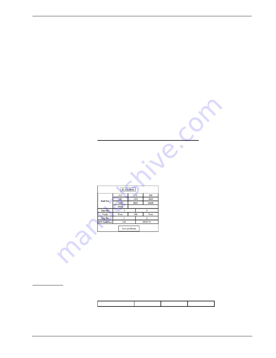
RS-232 Menu (Lectern-Mount Configurations Only)

Select the RS-232 button, located at the top of the second column of the Setup
Menu, to change the touchpanel display to the RS-232 Menu, shown below. The
RS-232 Menu specifies four parameters required for the touchpanel to use its RS-
232 serial port. Ten baud rate buttons, labeled 110, 150, 300, 600, 1200, 2400,
4800, 9600, 19200, and 38400, are available for selection. Also, select seven or
eight data bits; none, odd, or even parity; one or two stop bits.

RS-232 Menu

RTS/CTS handshaking is supported by the Series 3000 Touchpanels. If
handshaking is desired, select the RTS/CTS button. If no hardware handshaking is
needed, select the Off button. Selections for all RS-232 parameters are indicated
with light gray text. The parameters are factory set to 38.4 Kbd, eight data bits, no
parity bits, and one stop bit. Handware handshaking is factory set to Off.

Select the Save and Return button, located at the bottom of the RS-232 Menu, after
RS-232 parameters have been set.

RS-232 Protocol

Series 3000 Touchpanels support panel operation via a host computer through the
RS-232 port. Crestron recommends that the following serial data format is set.

Suggested Serial Data Format

Baud Rate: 38400

Data Bits: 8

Parity: None

Stop Bits: 1

These settings may be altered via the RS-232 Menu when configuring the
touchpanel, however, doing so may prevent Crestron supplied software from

Содержание BriteTouch 3000

Страница 1: ......

Страница 2: ......

Страница 3: ...cifications 6 Installation Setup 7 Identity Code 7 Recommended Cleaning 7 Preparation for Use 7 Hardware Hookup 8 Configuring the Touchpanel 9 Programming 15 Reserved Join Numbers 15 Workshop Versus S...

Страница 4: ......

Страница 5: ...h Series 3000 unit is to replace hard wired panels in either a CRESNET II or an RS 232 based control system The touchpanel is capable of replacing large complicated panels with a series of simpler scr...

Страница 6: ...cted from the rack or panel except during reprogramming For additional software information consult the help file available on the VTW installation disks Position Lock Button The position lock button...

Страница 7: ...h the touch of a single button regardless of the current page being displayed Physical Description Touchpanels The 9 6 inch 23 9 cm touch sensitive viewing screen is located on the front of each Serie...

Страница 8: ...0 Touchpanels Interface Module CN RJ11 NOTE All tiltcase Series 3000 touchpanels are supplied with a cable assembly that connects to the CN RJ11 supplied Pinout information is provided in this section...

Страница 9: ...ts are moveable and can tilt The B suffix identifies the touchpanel as having feature buttons The L suffix identifies the touchpanel as a lectern mount The 1M suffix identifies the touchpanel as havin...

Страница 10: ...CT 3000 CT 3000B CT 3000 1M Height 8 6 in 212 8 cm LC 3000 LC 3000B LC 3000 1M Width 11 2 in 28 5 cm Dimensions Weight Depth 7 0 in 17 8 cm without CN RJ11 Weight 5 5 lb 2 5 kg for CT configurations W...

Страница 11: ...ge quality For best cleaning results use a clean damp non abrasive cloth with any commercially available non ammonia glass cleaner Bezels may not provide a complete water tight seal Therefore apply cl...

Страница 12: ...II network cable shown below and appropriate interface module Recommended CRESNET II Network Cable Part No CRE 2S18218 NOTE Wire is available from Liberty Wire Cable 719 260 0061 CN RJ11 OR ANY LECTER...

Страница 13: ...le assembly is not supplied 4 Apply power to the touchpanel and observe illumination of the touch sensitive screen The touchpanel enters RUN MODE and displays a loaded panel page To enter SETUP MODE a...

Страница 14: ...he upper left corner Touch the corner of the screen to initiate calibration Another message Touch Lower Right Corner appears in the lower right corner Touch the corner of the screen to return to the M...

Страница 15: ...settings If parameters are saved the settings are restored in the event of a power failure The Save Setup button located just above the Return button in the corner of the Setup Menu may be selected a...

Страница 16: ...ng is disabled when the Panel Track button is deselected When disabled a given touchpanel does not respond to page changes made to other touchpanels on the network Panel tracking is factory set with t...

Страница 17: ...ave been set RS 232 Menu Lectern Mount Configurations Only Select the RS 232 button located at the top of the second column of the Setup Menu to change the touchpanel display to the RS 232 Menu shown...

Страница 18: ...form turns off a function sending back information received from the touchpanel i e jumping pins 2 and 3 makes the buttons momentary Notice that the touchpanel responds to P and R commands even when c...

Страница 19: ...the center of the button Save Setup and Run Program The Save Setup and Run Program button located at the upper right corner of the Main Menu saves all of the setup information to EEPROM and displays t...

Страница 20: ...n of the control system requirements The objects that are used in SIMPL are called symbols A basic touchpanel SIMPL program is shown below in block diagram form Series 3000 SIMPL Program The CRESNET I...

Страница 21: ...lustrations provide insight to a small portion of a CRESNET control system developed with SIMPL Windows To begin the programmer should envision the system in block diagram form shown below Block Diagr...

Страница 22: ...d assign signals to the Interlock symbol shown below Graphical Detail View of an Interlock in SIMPL Windows Programming Manager The signals from the Interlock are used as feedback into the touchpanel...

Страница 23: ...ectly calibrated Enter SETUP MODE and recalibrate Touchpanel is not Incorrect network wiring Touch screen to remove message and verify correct wiring to all connectors responding and screen displays N...

Страница 24: ...0 In Europe call Crestron International at 32 15 730 974 In Asia call Crestron Asia at 852 2341 2016 In Latin America call 525 574 15 90 For local support from exclusive Crestron factory trained perso...

Страница 25: ...er to be free from manufacturing defects in materials and workmanship for a period of three 3 years from the date of shipment to purchaser Disk drives and any other moving or rotating mechanical parts...

Страница 26: ......

Отзывы: