Crestron BriteTouch 3000 Скачать руководство пользователя страница 15

                                                                                   CRESTRON                                                                                   

Operations Guide - DOC. 8094B

Series 3000 Touchpanels  

••

  11

Setup Menu

Brightness

Screen brightness may need to be altered because of ambient light conditions or
personal preference. Three buttons, Brightness Low, Brightness Medium, and
Brightness High, located in the bottom row of the Setup Menu may be selected to
assign brightness setting. Current brightness setting is shown in light gray text .

Contrast

Screen contrast may need to be altered because of ambient light conditions, panel
temperature, or personal preference. Two contrast buttons, Contrast << and
Contrast >>, located in the two left-most columns of the middle row of the Setup
Menu may be held down for continuous and smooth adjustment of the screen.

Save Setup

It is advisable to regularly save setup parameters if the user is satisfied with the
settings. If parameters are saved, the settings are restored in the event of a power
failure. The Save Setup button located just above the Return button in the corner of
the Setup Menu may be selected at any time to save setup parameters. The button
text changes color from black to light gray text while in save mode.

Return

Select the Return button, located at the lower right corner of the Setup Menu, after
setup parameters have been set.

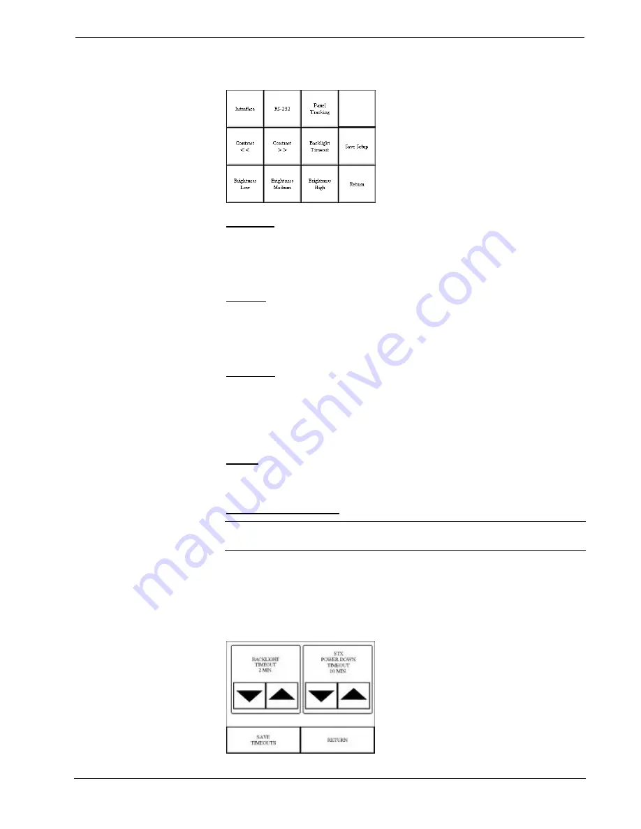
Backlight Timeout Menu

NOTE:  

Display backlight requires warm-up time. A display reaches 80% of its

final level in five minutes and full brightness in 20 minutes.

The touchpanel display hardware life can be lengthened by turning off the backlight
when the touchpanel is inactive. The Backlight Timeout button is located in the
middle row of the third column of the Setup Menu. Selection of this button changes
the touchpanel display to reveal the Backlight Menu, shown below. The length of
touchpanel inactivity can be specified to minimize power utilization.

Backlight Menu

Содержание BriteTouch 3000

Страница 1: ......

Страница 2: ......

Страница 3: ...cifications 6 Installation Setup 7 Identity Code 7 Recommended Cleaning 7 Preparation for Use 7 Hardware Hookup 8 Configuring the Touchpanel 9 Programming 15 Reserved Join Numbers 15 Workshop Versus S...

Страница 4: ......

Страница 5: ...h Series 3000 unit is to replace hard wired panels in either a CRESNET II or an RS 232 based control system The touchpanel is capable of replacing large complicated panels with a series of simpler scr...

Страница 6: ...cted from the rack or panel except during reprogramming For additional software information consult the help file available on the VTW installation disks Position Lock Button The position lock button...

Страница 7: ...h the touch of a single button regardless of the current page being displayed Physical Description Touchpanels The 9 6 inch 23 9 cm touch sensitive viewing screen is located on the front of each Serie...

Страница 8: ...0 Touchpanels Interface Module CN RJ11 NOTE All tiltcase Series 3000 touchpanels are supplied with a cable assembly that connects to the CN RJ11 supplied Pinout information is provided in this section...

Страница 9: ...ts are moveable and can tilt The B suffix identifies the touchpanel as having feature buttons The L suffix identifies the touchpanel as a lectern mount The 1M suffix identifies the touchpanel as havin...

Страница 10: ...CT 3000 CT 3000B CT 3000 1M Height 8 6 in 212 8 cm LC 3000 LC 3000B LC 3000 1M Width 11 2 in 28 5 cm Dimensions Weight Depth 7 0 in 17 8 cm without CN RJ11 Weight 5 5 lb 2 5 kg for CT configurations W...

Страница 11: ...ge quality For best cleaning results use a clean damp non abrasive cloth with any commercially available non ammonia glass cleaner Bezels may not provide a complete water tight seal Therefore apply cl...

Страница 12: ...II network cable shown below and appropriate interface module Recommended CRESNET II Network Cable Part No CRE 2S18218 NOTE Wire is available from Liberty Wire Cable 719 260 0061 CN RJ11 OR ANY LECTER...

Страница 13: ...le assembly is not supplied 4 Apply power to the touchpanel and observe illumination of the touch sensitive screen The touchpanel enters RUN MODE and displays a loaded panel page To enter SETUP MODE a...

Страница 14: ...he upper left corner Touch the corner of the screen to initiate calibration Another message Touch Lower Right Corner appears in the lower right corner Touch the corner of the screen to return to the M...

Страница 15: ...settings If parameters are saved the settings are restored in the event of a power failure The Save Setup button located just above the Return button in the corner of the Setup Menu may be selected a...

Страница 16: ...ng is disabled when the Panel Track button is deselected When disabled a given touchpanel does not respond to page changes made to other touchpanels on the network Panel tracking is factory set with t...

Страница 17: ...ave been set RS 232 Menu Lectern Mount Configurations Only Select the RS 232 button located at the top of the second column of the Setup Menu to change the touchpanel display to the RS 232 Menu shown...

Страница 18: ...form turns off a function sending back information received from the touchpanel i e jumping pins 2 and 3 makes the buttons momentary Notice that the touchpanel responds to P and R commands even when c...

Страница 19: ...the center of the button Save Setup and Run Program The Save Setup and Run Program button located at the upper right corner of the Main Menu saves all of the setup information to EEPROM and displays t...

Страница 20: ...n of the control system requirements The objects that are used in SIMPL are called symbols A basic touchpanel SIMPL program is shown below in block diagram form Series 3000 SIMPL Program The CRESNET I...

Страница 21: ...lustrations provide insight to a small portion of a CRESNET control system developed with SIMPL Windows To begin the programmer should envision the system in block diagram form shown below Block Diagr...

Страница 22: ...d assign signals to the Interlock symbol shown below Graphical Detail View of an Interlock in SIMPL Windows Programming Manager The signals from the Interlock are used as feedback into the touchpanel...

Страница 23: ...ectly calibrated Enter SETUP MODE and recalibrate Touchpanel is not Incorrect network wiring Touch screen to remove message and verify correct wiring to all connectors responding and screen displays N...

Страница 24: ...0 In Europe call Crestron International at 32 15 730 974 In Asia call Crestron Asia at 852 2341 2016 In Latin America call 525 574 15 90 For local support from exclusive Crestron factory trained perso...

Страница 25: ...er to be free from manufacturing defects in materials and workmanship for a period of three 3 years from the date of shipment to purchaser Disk drives and any other moving or rotating mechanical parts...

Страница 26: ......

Отзывы: