


DMS-R-IM
Interpreting HMI
April 7, 2021
Digital Modular System - Rinse
5-3
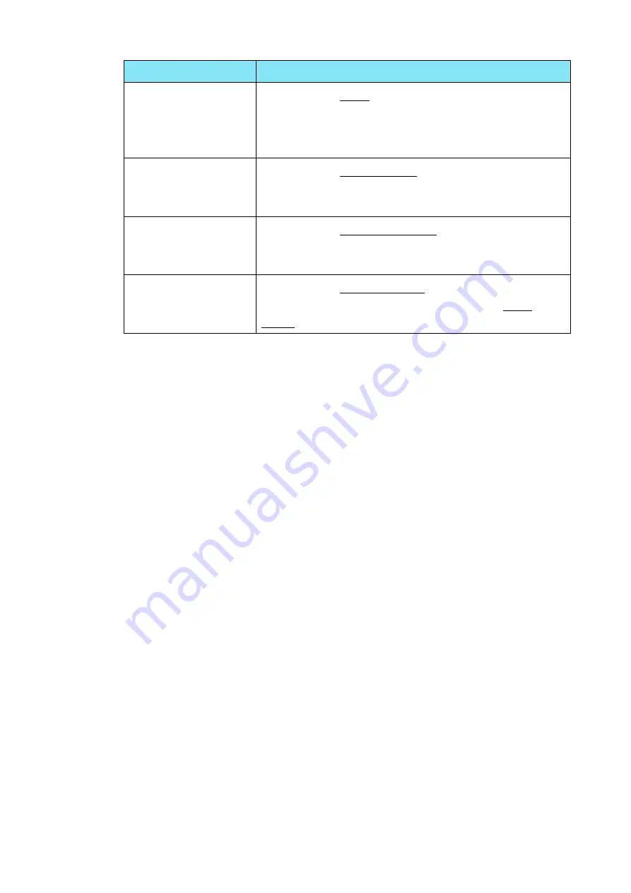
Button
Description
[Miscellaneous
Parameters]
Press to go to Misc. screens to set sonic power (%),
low sonic power (%) alarm set point and perform
LOCAL
and
REMOT
E mode switching. User can
change system date & time in this screen as well.
[Auto Options]
Press to go to Auto Options screen which is to enable
or disable station’s components or features such as
heater and pump for Auto mode operation.
[Digital I/O Status]
Press to go to Digital I/O status screen to monitor
input and output of PLC for troubleshooting
purposes.
[System ON]
Press to go to Console Power screen to turn ON the
system and press [Exit] button to return to Main
Menu screen.


