background image

18

ENGLISH

10

11

12

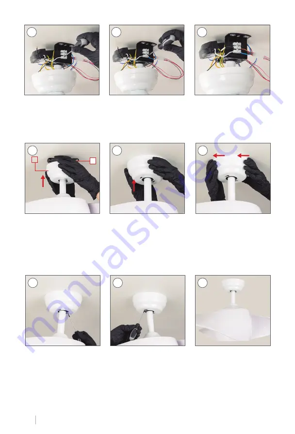
Connect the L cable of the 

driver to the PHASE cable 

of your installation.

Connect the N wire of the 

driver to the NEUTRAL wire 

of your installation.

Make sure everything is at-

tached correctly.

13

14

15

slide piece 

A

 upwards to fit it on the protruding screws of 

the piece  

K

Once  fitted,  turn  the  piece 

A

 toward the left. Make sure 

no wires get pinched.

Finally, with the help of a screwdriver, tighten the screws so that the piece is well fixed.

16

17

18

A

K

Содержание WIND FOLD

Страница 1: ...1 ENGLISH WIND FOLD CEILING FAN WITH LIGHT MANUAL ASSEMBLY ...

Страница 2: ......

Страница 3: ......

Страница 4: ...ger le manuel dans votre langue visitez notre site Web www create store com fr IT Per scaricare il manuale nella sua lingua visitare il nostro sito Web www create store com it DE UmdasHandbuch in Ihrer Sprachen herunterzuladen besuchen Sieunsere Website www create store com de NL Bezoek onze website om de handleiding in uw taal te downloaden www create store com nl PL Aby pobrać instrukcję w swoim...

Страница 5: ...ing 8 Step 1 False ceiling 10 Choice of grab bar 11 Step 2 Blade assembly 13 Step 3 Assembly of the main body 15 Step 4 Driver connection 16 Step 5 Fitting the trim 19 Step 6 Led board connection 20 Step 7 Placement of la tulipa 21 Blade balancing kit 22 WIND FOLD ...

Страница 6: ...ING KIT SUPPORT BLADES EMBELLISHER ENGINE BLADE SCREWS x3 BLADES SHANK EXTENSION POST MOUNTING BRACKET TULIPA DRIVER ENGINE REMOTE CONTROL LED PLATE SCREWS FOR TRIM ENGINE 2 WOOD SCREWS ATTENTION Before starting the as sembly remember to disconnect the light from the electrical panel so as not to suffer an electric shock ...

Страница 7: ... the hole in the wood Repeat this step on all 3 holes remaining Place the washer and then the screw M2 With the help of the screwdriver tighten the screws M2 Make sure the part K It is perfectly hooked to the ceiling and that no cable is trapped Mark with a pencil the 4 holes of the piece K in the roof K PARTS AND TOOLS M2 M2 MATERIAL NOT INCLUDED 2 K SUPPORT OF MOUNTING ...

Страница 8: ...t Mark with a pencil the 2 central holes of the piece K on the ceiling using the same piece as a guide K M1 M2 M1 M2 M3 M4 disassemble the part M separating it into pieces M M K PARTS AND TOOLS MATERIAL NOT INCLUDED Ø8mm 1 3 2 4 Only the thread part should protrude place the pieces M1 in the holes in the ceil ing SUPPORT OF MOUNTING ...

Страница 9: ...the ceiling cables are on one side of the piece K M1 K K M4 5 7 8 6 Enter the part in order M2 M3 and then the nut M4 Tighten the part M4 with a No 10 wrench until you feel it s ok fixed Make sure the part K It is perfectly hooked to the ceiling and no cable gets caught M2 M3 M4 ...

Страница 10: ...the ceiling to be able to continue with the assembly With the help of a drill make the 2 corre sponding holes Insert the fixing screws into the holes and make sure that the lever opens place the piece K and screw the fixing screws to the false ceiling Mark the 2 central holes of the piece on the ceiling with a pencil K using the same piece as a guide K X 3 5 4 2 K K 1 ...

Страница 11: ...u must follow the instructions below If you choose the height of the piece I go directly to step 2 page 12 Using a screwdriver remove the two screws on the bar tilt bracket I Slide the tilt stand down Remove the pin from the tilt bracket Carefully pull the pin out of the bar I Attach the tilt bracket to the bar J Place the pin of the tilt sup port on the bar J Pull out the bracket bar tilt I Pull ...

Страница 12: ...I Snap the tilt bracket onto the pin Tighten the two screws on the tilt bracket with the screwdriver Put the pin back in the piece J Secure the pin with the locking piece so that it does not come out The piece is already J ready to use ...

Страница 13: ... H if your screws Q are in a plastic bag go to step 4 Q Remove the blade support bolts R and save them for the next step Start placing the blades E screwing the screws Q from the bottom of the engine H as shown in the images Remember to tighten the screws gradually x7 SCREWS BLADES BLADE SUPPORT H ENGINE ...

Страница 14: ... screws Q to the engine H rotate the center piece so that the driver cables are facing up Place the blade support R on top of engine H and below the blades E tighten the blade E with the screws you removed from the blade holder R Keep screwing the rest of the blades E just like the first one did ...

Страница 15: ...t A Insert the seatpost I J through the hole in the part L Once the piece is inserted A Y L you must insert the cables of the part H inside the bar If you want you can secure the wires with elec trical tape to make it easier to pass them through STEP 3 ASSEMBLY OF THE MAIN BODY O CHOOSE THE HEIGHT YOU NEED FLOWER ENGINE A I J H L EMBELLISHER ENGINE ...

Страница 16: ...y attached Once the stem is well an chored to the piece H the main body of the fan motor will be assembled 12 H 7 8 9 H Insert the seatpost into the top of the piece H Make sure no wires get pinched Once the seatpost has been inserted place the pin of the piece I J so that it matches the hole in the seatpost With the help of a screw driver remove the 2 screws from the top of the piece H ...

Страница 17: ...ion You will need to attach the remaining wires from the piece B and the phase and neutral cables of its instal lation in the strip of the piece K as it s shown in the following Once connected place the part O screwing it on until it is secure K 1 2 3 Put the tilt bracket into the slot on the part K Remember to set the notch on the tilt bracket back so that the piece fits snugly Before continuing ...

Страница 18: ...EUTRAL wire of your installation Make sure everything is at tached correctly 13 14 15 slide piece A upwards to fit it on the protruding screws of the piece K Once fitted turn the piece A toward the left Make sure no wires get pinched Finally with the help of a screwdriver tighten the screws so that the piece is well fixed 16 17 18 A K ...

Страница 19: ...ed bag use them for this step Pass the fan cables through the center hole of the piece G Then firmly tighten the screws used in step 1 so that the part G is properly fastened 1 4 2 5 7 6 3 G G place the piece G aligning the holes with the holes in the motor Leave the blue and white wires coming out of the hole EMBELLISHER SCREWS FOR EMBELLISHER ...

Страница 20: ... wires D to those of the fan joining the connections each cable with its same color Then attach the part D to the fan with the help of the magnets so that it stays in place 1 4 2 5 3 6 D D D D STEP 6 LED BOARD CONNECTION LED PLATE ...

Страница 21: ...e fan by fitting it into the trim and turn it clockwise Do not forget to check that the piece is well secured Once checked you can connect the electricity and enjoy your new fan with light 1 2 3 STEP 7 PLACEMENT OF LA TULIPA F F TULIPA ...

Страница 22: ...not aligned you can carefully bend the bracket up or down a bit to align with each other If the balance problem is not solved even by following the steps above you must perform a dynamic balance using the kit provided Follow this procedure 1 Turn on the fan and set the speed at which the most sway is generated normally occurs at the highest speed 2 Turn off the fan Select a blade and place the bal...

Страница 23: ......

Страница 24: ...24 ENGLISH ...

Отзывы: