Lep SC130B1002-2EN
Issued 03-08
1002-3
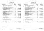
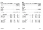
COMPONENT WEIGHT .................................................................................................................................................22
Major component weight (CX130B)............................................................................................................................22
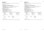
COMPONENT WEIGHT .................................................................................................................................................23
Major component weight (CX130B 2PC, CX130B 2PC (with Blade)) ........................................................................23
Other component weight.............................................................................................................................................24
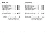
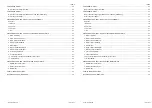
DIMENSIONS AND WEAR LIMIT OF THE TRACK ASSEMBLY ...................................................................................18
Sprocket......................................................................................................................................................................18
Idler wheel ..................................................................................................................................................................19
Upper roller .................................................................................................................................................................20
Lower roller .................................................................................................................................................................21
Track...........................................................................................................................................................................22
DIMENSIONS AND WEAR LIMITS OF ATTACHEMENT MOBILE JOINTS ..................................................................23
1. Boom foot/Frame ....................................................................................................................................................23
2. Boom cylinder foot/Frame.......................................................................................................................................24
3. Boom cylinder head/Boom......................................................................................................................................24
4. Dipper cylinder foot/Boom ......................................................................................................................................25
5. Boom/Dipper...........................................................................................................................................................25
6. Dipper cylinder head/Dipper ...................................................................................................................................26
7. Bucket cylinder foot/Dipper.....................................................................................................................................26
8. Connecting rod/Dipper............................................................................................................................................27
9. Compensator/Bucket ..............................................................................................................................................27
10. Connecting rod/Compensator/Bucket cylinder head ............................................................................................28
11. Dipper/Bucket .......................................................................................................................................................29
DIMENSIONS AND WEAR LIMITS OF BLADE MOBILE JOINTS .................................................................................30
1. Blade/Blade cylinder head ......................................................................................................................................30
2. Blade cylinder foot/Frame.......................................................................................................................................31
3. Blade/Frame ...........................................................................................................................................................31
SPECIAL TORQUE SETTINGS......................................................................................................................................32
MACHINE OVERALL DIMENSIONS ..............................................................................................................................36

