background image

1001-4

 Lep 7-27691EN

Issued 02-06

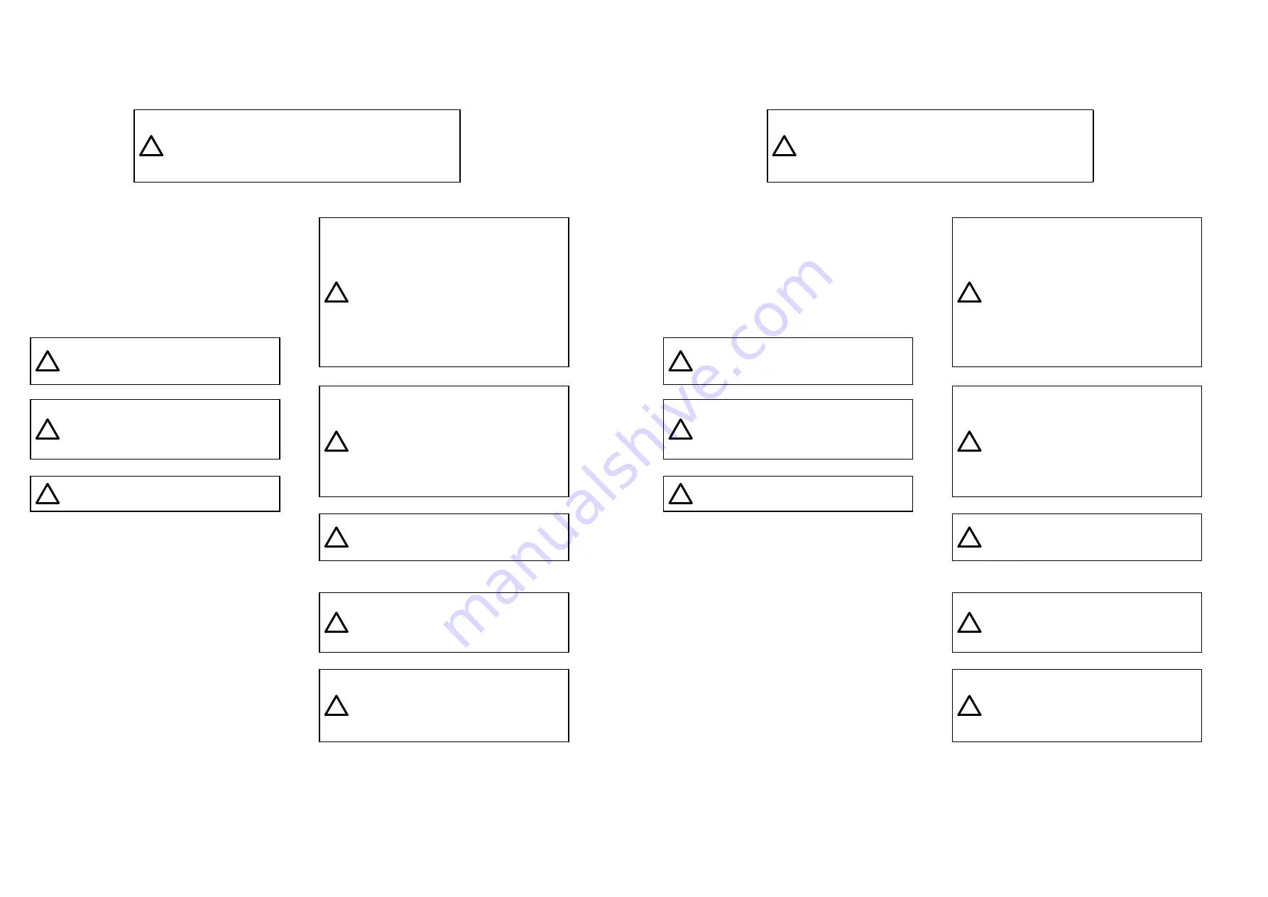
SAFETY

This symbol means ATTENTION! BECOME ALERT! YOUR
SAFETY IS INVOLVED. The message that follows the
symbol contains important information about safety. Carefully
read the message. Make sure you fully understand the
causes of possible injury or death.

!

To prevent injury always follow the Warning, Caution
and Danger notes in this section and throughout the
manual.

Put the warning tag shown below on the key for the
keyswitch when servicing or repairing the machine.
One warning tag is supplied with each machine.
Additional tags Part Number 331-4614 are available
from your service parts supplier

.

WARNING: Read the operator’s manual to
familiarize yourself with the correct control
functions.

!

WARNING: Operate the machine and
equipment controls from the seat position
only. Any other method could result in
serious injury.

!

WARNING: This is a one man machine, no
riders allowed.


!

WARNING: Before starting engine, study
Operator’s Manual safety messages. Read
all safety signs on machine. Clear the area of
other persons. Learn and practice safe use
of controls before operating.
It is your responsibility to understand and
f o l l o w   m a n u f a c t u r e r s   i n s t r u c t i o n s   o n
machine operation, service and to observe
pertinent laws and regulations. Operator’s
and Service Manuals may be obtained from
your Case dealer.

!

WARNING: If you wear clothing that is too
loose or do not use the correct safety
equipment for your job, you can be injured.
Always wear clothing that will not catch on
objects. Extra safety equipment that can be
required includes hard hat, safety shoes, ear
protection, eye or face protection, heavy
gloves and reflector clothing.

!

WARNING: When working in the area of the
fan belt with the engine running, avoid loose
clothing if possible, and use extreme caution.

!

WARNING: When doing checks and tests
on the equipment hydraulics, follow the
procedures as they are written. DO NOT
change the procedure.

!

WARNING: When putting the hydraulic
cylinders on this machine through the
necessary cycles to check operation or to
remove air from a circuit, make sure all
people are out of the way.

!
Содержание CX130B

Страница 1: ...wing reduction gear 6004 SM130B6004 0EN 7 UNDERCARRIAGE HYDRAULICS Consult the Engine Service Manual Copyright 2008 CNH France S A Printed in France CNH Lep SM130BTOC 1EN November 2008 CRAWLER EXCAVATOR CX130B SERVICE MANUAL TABLE OF CONTENTS DIVISION SECTION SECTION N REFERENCE N 1 GENERAL INFORMATION Safety general information and standard torque data 1001 7 27691EN General specifications and sp...

Страница 2: ...ade in accord ance with the technical specifications known as of the date of design of this document Lep SM130BTOC 1EN Issued 11 08 DIVISION SECTION SECTION N REFERENCE N 8 UPPERSTRUCTURE HYDRAULICS Depressurising and decontaminating the hydraulic system use of the vacuum pump and bleeding the components 8000 SM160B8000 0EN Specifications troubleshooting checks and hydraulic pressure settings 8001...

Страница 3: ...e February 2006 Lep 7 27691EN 1001 SAFETY GENERAL INFORMATION AND TORQUE SPECIFICATIONS Section 1001 CNH Copyright 2006 CNH France S A Printed in France February 2006 Lep 7 27691EN 1001 SAFETY GENERAL INFORMATION AND TORQUE SPECIFICATIONS Section 1001 ...

Страница 4: ...ver you see this symbol carefully read the message that follows as there is a risk of serious injury 1001 2 Lep 7 27691EN Issued 02 06 TABLE OF CONTENTS GENERAL INFORMATION 3 SAFETY 4 STANDARD TORQUE DATA FOR CAP SCREWS AND NUTS 6 WARNING This symbol is used in this manual to indicate important safety messages Whenever you see this symbol carefully read the message that follows as there is a risk ...

Страница 5: ...more information Please click here Then get the complete manual NOTE If there is no response to click on the link above please download the PDF document first and then click on it Have any questions please write to me admin servicemanualperfect com ...

Страница 6: ...ice Manuals Failures due to the use of non specified oils and lubricants are not covered by warranty 1001 3 Lep 7 27691EN Issued 02 06 GENERAL INFORMATION Cleanning Clean all metal parts except bearings in a suitable cleaning solvent or by steam cleaning Do not use caustic soda for steam cleaning After cleaning dry and put oil on all parts Clean oil passages with compressed air Clean bearings in a...

Страница 7: ...ry cycles to check operation or to remove air from a circuit make sure all people are out of the way 1001 4 Lep 7 27691EN Issued 02 06 SAFETY This symbol means ATTENTION BECOME ALERT YOUR SAFETY IS INVOLVED The message that follows the symbol contains important information about safety Carefully read the message Make sure you fully understand the causes of possible injury or death To prevent injur...

Страница 8: ...tery at full charge If you do not follow these instructions you or others in the area can be injured 1001 5 Lep 7 27691EN Issued 02 06 WARNING Use insulated gloves or mittens when working with hot parts WARNING Lower all attachments to the ground or use stands to safely support the attachments before you do any maintenance or service WARNING Pin sized and smaller streams of hydraulic oil under pre...

Страница 9: ...g torque Nm 8 8 21 6 42 1 78 5 117 7 176 5 245 2 343 2 lb ft 6 5 15 9 31 1 57 9 86 9 130 2 181 253 2 1001 6 Lep 7 27691EN Issued 02 06 STANDARD TORQUE DATA FOR CAP SCREWS AND NUTS Tightening of cap screws nuts Tighten alternately so that tightening torque can be applied evenly The numbers in the figure below indicate the order of tightening JS00481A Cap screws which have had Loctite used white res...

Страница 10: ...rance S A Printed in France March 2008 Lep SC130B1002 2EN SPECIFICATIONS AND SPECIAL TORQUE SETTINGS Section 1002 1002 CNH Copyright 2008 CNH France S A Printed in France March 2008 Lep SC130B1002 2EN SPECIFICATIONS AND SPECIAL TORQUE SETTINGS ...

Страница 11: ...ages Whenever you see this symbol carefully read the message which follows Your safety depends on it Lep SC130B1002 2EN Issued 03 08 1002 2 TABLE OF CONTENTS TYPE SERIAL NUMBER AND YEAR OF MANUFACTURE OF THE MACHINE 4 Machine 4 Engine 4 Serial numbers of the components 4 FLUIDS AND LUBRICANTS 5 Hydraulic fluid 5 Transmission component oil 5 Grease 5 Engine Oil 6 Engine fuel maintenance of fuel fil...

Страница 12: ...ade cylinder foot Frame 31 3 Blade Frame 31 SPECIAL TORQUE SETTINGS 32 MACHINE OVERALL DIMENSIONS 36 Lep SC130B1002 2EN Issued 03 08 1002 3 COMPONENT WEIGHT 22 Major component weight CX130B 22 COMPONENT WEIGHT 23 Major component weight CX130B 2PC CX130B 2PC with Blade 23 Other component weight 24 DIMENSIONS AND WEAR LIMIT OF THE TRACK ASSEMBLY 18 Sprocket 18 Idler wheel 19 Upper roller 20 Lower ro...

Страница 13: ...ers of the components Hydraulic pump Swing reduction gear Travel reduction gears Control valve 1 3 2 Lep SC130B1002 2EN Issued 03 08 1002 4 TYPE SERIAL NUMBER AND YEAR OF MANUFACTURE OF THE MACHINE For all part orders request for information or assistance always specify the type and the serial number of the machine to your Case dealer Fill in the following lines with the required information Type ...

Страница 14: ... 251H EP NLGI 2 WARNING The conditions of use for individual fluids and lubricants must be respected Lep SC130B1002 2EN Issued 03 08 1002 5 FLUIDS AND LUBRICANTS Lubricants must have the correct properties for each application Hydraulic fluid CASE AKCELA hydraulic fluid is specially designed for high pressure applications and for the CASE hydraulic system The type of fluid to be used depends on th...

Страница 15: ...ty Oil range CT02M001 1 With mineral base 2 With semi synthetic base 3 With synthetic base 3 3 1 2 2 Lep SC130B1002 2EN Issued 03 08 1002 6 Engine Oil THE CASE AKCELA No 1 engine oil is recommended for your engine This oil ensures proper lubrication of your engine for all operating conditions If the CASE AKCELA Multigrade No 1 ENGINE OIL cannot be obtained use the oil corresponding to one of the f...

Страница 16: ...motive Engineers Based on SAE J 313C NO 2 D BS British Standard Based on BS 2869 197 Class A 1 EN590 Lep SC130B1002 2EN Issued 03 08 1002 7 Engine fuel maintenance of fuel filters and fuel storage In order to meet the emission control regulation of 3rd stage the engine components have been made precisely and they are to be used under high pressure conditions Therefore the specified fuel must be us...

Страница 17: ...every morning In addition remove the cover under the tank once a year to clean up inside of the tank Lep SC130B1002 2EN Issued 03 08 1002 8 If the fuel is mixed with the engine oil the oil is diluted to deteriorate its lubricating property resulting in accelera tion of wear Water content allows inside of the fuel tank to rust which in turn blocking the fuel line and the fuel filter IMPORTANT In co...

Страница 18: ... use of petrol kerosene paint solvents etc causes discoloration cracks or deformation of these parts Lep SC130B1002 2EN Issued 03 08 1002 9 Fuel storage Long storage can lead to the accumulation of impurities and condensation in the fuel Engine trouble can often be traced to the presence of water in the fuel The storage tank must be placed outside and the temperature of the fuel should be kept as ...

Страница 19: ...11 in 7785 mm 306 49 in Height with attachment 2810 mm 110 62 in 2710 mm 106 69 in 2820 mm 111 02 in Lep SC130B1002 2EN Issued 03 08 1002 10 SPECIFICATIONS Main data Model name CX130B CX130B LC CX130B Blade CX130B 2PC CX130B 2PC with Blade Hydraulic Excavator Operating weight CX130B 12700 kg 27999 lbs CX130B LC 13000 kg 28660 lbs CX130B Blade 13500 Kg 29762 lbs CX130B 2PC 13200 Kg 29101 lbs CX130B...

Страница 20: ...45 in 7890 mm 310 63 in Height with attachment 2730 mm 107 48 in 2650 mm 104 33 in 2780 mm 109 45 in Lep SC130B1002 2EN Issued 03 08 1002 11 Main body dimensions Main body width and length See machine overall dimensions Upper side swing body width 2540 mm 100 in Cab width 1000 mm 39 37 in Main body height 2820 mm 111 02 in Tail swing radius 2130 mm 83 86 in Swing body tail distance 2130 mm 83 86 i...

Страница 21: ...lter inside housing 8 µm Fuel filter Main filter 4 µm Pre filter 10 µm Pre filter 2PC 2PC Blade 7 µm Lep SC130B1002 2EN Issued 03 08 1002 12 Engine Name ISUZU 4JJ1X Type 4 cycle water cooled overhead camshaft vertical in line direct injection type electronic control with turbocharger No of cylinders bore x stroke 4 Ø95 4 mm x 104 9 mm 3 76 x 4 13 in Displacement 2999 cc 183 cu in Compression ratio...

Страница 22: ... Engine emergency stop Working light Cab top 24V 70W x1 Boom up 24V 70W x1 Interior light 24V 10W x1 Lep SC130B1002 2EN Issued 03 08 1002 13 Operating devices Operator s seat Location left side Structure Adjustable forward and back and up and down reclining mechanism with seat suspension Cab Sealed steel type all reinforced glass Levers and pedals For travel use Lever and pedal type hydraulic pilo...

Отзывы: