background image

5


B-3) Liquid Level Controls: 

It is recommended to use a liquid level control system 

that allows the on and off point to be separated by at least 

twelve inches. An additional set point (lag point) should 

be incorporated with an alternator switching system for 

a duplex (two pump) station. A high level alarm may be 

required to alert maintenance personnel that there is a 

high water situation in the wet well should the output of the 

pump station drop below the inflow rate. A low level cut off 

may be installed to provide system shutdown if the main 

level control system malfunctions. The off point should be 

positioned so that the liquid level never drops below the 

minimum continuous duty point for the pump shown in 

Figure 1.

B-4.1) Electrical Connections:

WARNING! - All model pumps and 

control panels must be properly 

grounded per the NATIONAL 

ELECTRIC CODE or CANADIAN 

ELECTRIC CODE, State, Province 

and local codes. Improper 

grounding voids warranty.

B-4) Power/Control Cord:


The cord assembly mounted to the pump must not be 

modified in any way except for shortening to a specific 

application. Any splice between the pump and the control 

panel must be made in accordance with all applicable 

electric codes. It is recommended that a junction box (if 

used) be mounted outside the sump or be of at least Nema 

6 or 6P construction with NEMA 6 or 6P watertight cord 

grips if located within the wet well. A water and vapor tight 

seal fitting 

MUST

 be used in conduit leaving the wet well 

to prevent moisture and gases from reaching the control 

panel. Prior to installation, the pump power cable should be 

inspected for nicks or damage. If damaged, the cord should 

be replaced before installation. 

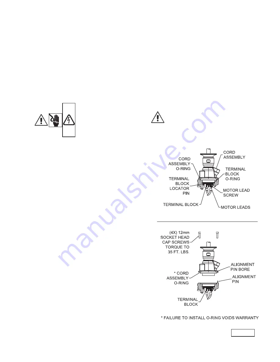
Install the cord assembly o-ring onto the cord assembly 

as shown in Figure 2. Align the hole in the cord assembly 

with the alignment pin in the motor cap. Lower the cord 

assembly into the bore of the motor cap taking care to keep 

the pins aligned. Push the cord assembly into the motor 

housing until fully engaged. Install the four 12mm socket 

head cap scews through the cord assembly into the motor 

cap. Slowly tighten the four screws alternating in a cross 

pattern until the cord assembly is drawn down flush to the 

motor cap. The screws should then be torqued to 35 ft. lbs.

CORD CLAMPING PLATE SHOULD BE DRAWN METAL 

TO METAL (35 FT/LBS BOLT TORQUE). IF A GAP 

EXISTS CONTINUE TO TIGHTEN BOLTS. DO NOT USE 

ANY TYPE OF SEALANT OR GREASE ON THE CORD 

ENTRY.

DO NOT USE THE POWER CORD TO LIFT PUMP.

NOTE: The White Wire Is Not A Neutral Or Ground 

Lead. The Black, White And Red Leads Are Power 

Carrying Conductors. The Green Lead Is For 

Connection To Ground.

B-4.1) Electrical Connections:

When the electrical connections are made, the lead wires 

from the power cable should be stripped so that the ground 

wire is at least two inches longer than the power leads. 

This will ensure that if the cable is inadvertently pulled out 

of the connection point, the ground wire will be the last lead 

to break the circuit.

B-4.2) Wire Size:


If additional cable is required consult a qualified electrician 

for proper wire size. Voltage drop due to wire resistance 

between the pump and power connection point should be 

limited to 3% when additional cable is added.

WARRANTY NOTE: 

Both the temperature sensor and moisture 

detection system must be connected to the 

motor circuitry such that the motor will be de-

energized or sound alarm if excessive motor 

temperatures are reached and/or if water is 

detected in the seal chamber and/or motor 

chamber. Failure to have the above mentioned 

systems installed and operative, nullifies 

warranty.

FIGURE 2

Содержание DEMING 7365 Series

Страница 1: ...ex Pumps 75 100HP 1750RPM 50 75HP 1150RPM 40HP 870RPM 6M Monovane Pumps 75 100HP 1750RPM 6D Dual Vane Pumps 75 100HP 1750RPM 8V Vortex Pumps 50 100HP 1150RPM 40 50HP 870RPM 8D Dual Vane Pumps 75HP 1750RPM 8T Tri Vane Pumps 75 150HP 1750RPM 50 100HP 1150RPM 40 50HP 870RPM 10D Dual Vane Pumps 50 100HP 1150RPM 40 50HP 870RPM 10T Tri Vane Pumps 50 100HP 1150RPM Series 7365 This product may be covered ...

Страница 2: ...UBLE SHOOTING 15 RECOMMENDED MINIMUM SUCTION CLEARANCE Fig 9 16 XSH CROSS SECTIONS FIG 5 6 EXPLODED VIEWS FIG 7 8 17 18 PARTS LISTS 19 WARRANTY 21 RETURNED GOODS POLICY 22 WARRANTY REGISTRATION 22 START UP REPORT 23 24 Other brand and product names are trademarks or registered trademarks of their respective holders Deming is a registered trademark of Crane Pumps Systems Inc 2016 Alteration Rights ...

Страница 3: ...ar eye protection when working on pumps Make sure lifting handles are securely fastened each time before lifting DO NOT operate pump without safety devices in place Always replace safety devices that have been removed during service or repair Secure the pump in its operating position so it can not tip over fall or slide DO NOT exceed manufacturers recommendation for maximum performance as this cou...

Страница 4: ...ephone 937 778 8947 or Crane Pumps Systems Canada in Brampton Ontario 905 457 6223 SECTION B INSTALLATION B 1 Location These self contained pumping units are recommended for use in a sump lift station or basin This pump is designed for submerged continuous duty 15 minutes duty in air at nameplate horsepower pumping sewage effluent wastewater or other nonexplosive or noncorrosive liquids not above ...

Страница 5: ...rd assembly o ring onto the cord assembly as shown in Figure 2 Align the hole in the cord assembly with the alignment pin in the motor cap Lower the cord assembly into the bore of the motor cap taking care to keep the pins aligned Push the cord assembly into the motor housing until fully engaged Install the four 12mm socket head cap scews through the cord assembly into the motor cap Slowly tighten...

Страница 6: ... 82 30N 4DH 13 00 330 75 575 3 60 1750 G 86 7 1 15 96 6 462 4 5 138319 2 4 18 4 2 4 18 4 095 7365 414 68 30N 4DH 14 57 370 100 460 3 60 1750 E 136 6 1 15 155 3 578 0 5 138319 2 4 18 4 2 4 18 4 070 7365 414 83 30N 4DH 14 57 370 100 575 3 60 1750 E 109 2 1 15 124 2 462 4 5 138319 2 4 18 4 2 4 18 4 095 7365 617 67 30N 6MH 13 78 350 75 460 3 60 1750 G 108 4 1 15 120 7 578 0 5 138319 2 4 18 4 2 4 18 4 ...

Страница 7: ...60 1150 H 87 4 1 15 95 6 489 6 5 138319 2 4 18 4 2 4 18 4 113 7365 658 68 30N 6VT 14 37 365 100 460 3 60 1150 E 135 0 1 0 135 0 612 0 5 138319 2 4 18 4 2 4 18 4 077 7365 658 83 30N 6VT 14 37 365 100 575 3 60 1150 E 108 0 1 0 108 0 489 6 5 138319 2 4 18 4 2 4 18 4 069 7365 659 94 30N 6VT 14 76 375 40 460 3 60 870 F 62 2 1 15 69 4 275 0 5 138318 6 4 18 4 6 4 18 4 166 7365 659 1D 30N 6VT 14 76 375 40...

Страница 8: ...7 0 800 0 5 138320 1 0 4 18 4 1 0 4 18 4 049 7365 850 1G 30N 8T 12 40 315 150 575 3 60 1750 D 159 5 1 0 159 5 640 0 5 138320 1 0 4 18 4 1 0 4 18 4 065 7365 823 95 30N 8T 13 19 335 50 460 3 60 1150 H 76 4 1 15 84 0 400 0 5 138318 6 4 18 4 6 4 18 4 130 7365 823 1E 30N 8T 13 19 335 50 575 3 60 1150 H 61 2 1 15 67 2 320 0 5 138318 6 4 18 4 6 4 18 4 189 7365 823 96 30N 8T 13 78 350 60 460 3 60 1150 F 8...

Страница 9: ...410 75 575 3 60 1150 H 87 4 1 15 95 6 489 6 5 138319 2 4 18 4 2 4 18 4 113 7365 X52 68 30N 10DL 17 32 440 100 460 3 60 1150 E 135 0 1 0 135 0 612 0 5 138319 2 4 18 4 2 4 18 4 077 7365 X52 83 30N 10DL 17 32 440 100 575 3 60 1150 E 108 0 1 0 108 0 489 6 5 138319 2 4 18 4 2 4 18 4 113 7365 X53 94 30N 10DL 17 32 440 40 460 3 60 870 F 62 2 1 15 69 4 275 0 5 138318 6 4 18 4 6 4 18 4 166 7365 X53 1D 30N ...

Страница 10: ...symbol An external ground screw is provided on the side of the motor cap which can be used for supplemental bonding connection where local codes permit or require such connection THREE PHASE 460 575 VOLT AC Power Cable Motor Lead ID Green Ground Green Black 1 Red 2 White 3 MOISTURE AND TEMPERATURE SENSORS MOISTURE AND TEMPERATURE SENSORS Control Cable Control Cable Lead ID Lead ID Black P1 Tempera...

Страница 11: ...UST be connected in series with the pilot circuit of the magnetic motor controller located in the control panel so that the thermostat will open the circuit before dangerous temperatures are reached A manual momentary start switch is required to prevent the automatic restarting of the motor when the thermostat resets refer to Figure 4 In the event of an over temperature condition the source of thi...

Страница 12: ...mation stamped on the pump s identification plate to the available power C 2 Check Pump Rotation Before putting pump into service for the first time the motor rotation must be checked Improper motor rotation can result in poor pump performance and can damage the motor and or pump To check the rotation suspend the pump freely momentarily apply power and observe the kickback Kickback should always b...

Страница 13: ...on seal plate pilot diameter lining up holes and install impeller and motor assembly onto volute Loctite cap screws insert into volute and motor assembly and torque to 35 ft lbs Check for free rotation of motor and impeller CAUTION Pressure builds up extremely fast increase pressure by tapping air nozzle Too much pressure will damage seal Do Not exceed 10 P S I in seal chamber TABLE 2 COOLING OIL ...

Страница 14: ...ordering replacement parts ALWAYS furnish the following information 1 Pump serial number and date code Paragraph F 4 2 Pump model number Paragraph F 3 3 Pump part number Paragraph F 2 4 Part description 5 Item part number 6 Quantity required 7 Shipping instructions 8 Billing Instructions F 2 PART NUMBER This number is used for ordering and obtaining information F 3 MODEL NUMBER This designation co...

Страница 15: ...eller for freedom of operation security and condition Clean impeller and inlet of any obstruction 9 Loosen union slightly to allow trapped air to escape Verify that turn off level of switch is set so that the suction is always flooded Clean vent hole 10 Check rotation If power supply is three phase reverse any two of three power supply leads to ensure proper impeller rotation 11 Repair fixtures as...

Страница 16: ...IED BY OTHERS 2 PIPE GUIDE RAILS SUPPLIED BY OTHERS PROOF COIL HOT GALVANIZED CHAIN OPTIONAL ATTACH OPTIONAL LIFTING CHAIN TO COLD SHUT FORCE CLOSED AND WELD BAF 6X6 SHOWN SHIM GROUT DIM A DIM B DIM C MODEL NUMBER DIM A INCHES MM 3VC 3 00 76 2 3VR 3VRA 3 50 88 9 3MA 4M 3 75 95 3 4D 4VL 4 00 101 6 4VH 4VHA 4 25 108 4ML 4DM 4MM 4 75 120 7 6V 5 25 133 4 6DL 5 50 139 7 4MB 6 00 152 4 4MH 4MHA 4DH 6ML ...

Страница 17: ...on proof rating impeller lower mechanical seal volute and power cord Service to any other components WILL VOID the warranty and explosion proof certification Any further work required contact Crane Pumps Systems Cross Sections FIGURE 9 FIGURE 10 Vortex Enclosed Items Not Shown 60 70 ...

Страница 18: ...18 Exploded Views FIGURE 11 FIGURE 12 Vortex Enclosed Items Not Shown 60 70 ...

Страница 19: ...0 ƒ Screw SHCS M18 x 2 50 x 50 18 8 SS 8A 1 138543 ƒ Washer Impeller 75 x 2 44 18 8 SS 9 1 See Table O Ring Volute Buna N 10 1 See Table Volute Cast Iron 11 2 See Table Wear Ring Volute Bronze 11A 2 See Table ƒ Wear Ring Impeller Bronze 19 1 130063 Ring Retaining EXT 5100 187 H 23 1 138550 Handle Lifting SS 56 1 See Table β Cord 59 1 See Table β π O Ring Cord Buna N 60 1 2 31003 248 Retainer Seal ...

Страница 20: ...20 Notes ...

Страница 21: ...es between the results of field testing conducted by or for user and laboratory tests corrected for field performance the latter shall control RECOMMENDATIONS FOR SPECIAL APPLICATIONS OR THOSE RESULTING FROM SYSTEMS ANALYSES AND EVALUATIONS WE CONDUCT WILL BE BASED ON OUR BEST AVAILABLE EXPERIENCE AND PUBLISHED INDUSTRY INFORMATION SUCH RECOMMENDATIONS DO NOT CONSTITUTE A WARRANTY OF SATISFACTORY PE...

Страница 22: ... Hazards In Handling Said Material All Applicable Laws And Regulations Shall Apply IMPORTANT WARRANTY REGISTRATION Your product is covered by the enclosed Warranty To complete the Warranty Registration Form go to http www cranepumps com ProductRegistration If you have a claim under the provision of the warranty contact your local Crane Pumps Systems Inc Distributor IMPORTANT WARRANTY INFORMATION W...

Страница 23: ...O___ Type _________________________________ Number and size of short circuit device s ___________ Amp rating ___________________ Overload Type _____________ Size ______________ Amp rating ___________________ Do protection devices comply with pump and motor Amp rating YES___ NO___ Are all electrical and panel entry connections tight YES___ NO___ Is the interior of the panel dry YES___ NO___ Liquid ...

Страница 24: ...l controls installed away from turbulence YES___ NO___ Is level control operating properly YES___ NO___ Is pump fully submerged during operation YES___ NO___ Follow up Corrective Action Required YES___ NO___ Additional Comments ____________________________________________________________________________ ____________________________________________________________________________ __________________...

Отзывы: