6
D. MAINTENANCE
1. LUBRICATION
BEARINGS -
Motor bearings should have periodic attention
and lubrication in accord with motor manufacturer’s
recommendations. Under ordinary conditions a ball bearing
will run from 10°F to 60°F above ambient temperatures.
Unless bearing temperature runs extremely hot do not
become alarmed.
PACKING -
On standard-fi tted, bronze-fi tted and all-bronze
construction, the stuffi ng box is lubricated by liquid being
pumped thru a by-pass tube. On all-iron construction, the
by-pass tube is eliminated and a grease fi tting installed
for stuffi ng box lubrication. A “water pump” grease is
recommended for the grease cup. If the liquid being pumped
is abrasive, a fresh water supply should be connected to the
stuffi ng box instead of the grease fi tting or by-pass tube.
SINGLE SEAL -
Single seals normally are lubricated and
cooled by the liquid returned to the seal chamber thru by-
pass tube.
DOUBLE SEAL
- Double seals should be cooled and
lubricated by sealing liquid under pressure, such as clear
water. If the pressure at the inner face of the seal is under
25 psi and the liquid temperature is under the boiling point,
a spring-loaded compression type grease cup, fi lled with
Standard Artic No. “0” grease or equal, may be used if
suitable sealing liquid is not available.
2. PROPER ADJUSTMENT of STUFFING BOX
The liquid being pumped should constantly, yet slowly, drip
from the stuffi ng box gland (16) when the pump is running.
This slow drip lubricates the shaft sleeve (3) and prevents
scoring.
NEVER
tighten the gland so as to entirely stop
the leakage through stuffi ng box. See Section “Repacking
Standard Stuffi ng Box”.
E - REPAIR
WARNING -
If pumping any fl uid that
could cause bodily injury (hot water,
caustic, etc.), always use eye protection
and wear protective clothing over all
exposed body areas.
REMOVE AND LOCK-OUT POWER TO THE
DRIVER WHILE PERFORMING THESE TASKS
Be sure that no one can accidentally restore power while
the pump is being serviced.
1. DISASSEMBLY OF LIQUID END -
The following
procedure is for the complete disassembly of the pump.
If complete disassembly is not necessary, use only
those steps which apply.
a. Slowly remove drain plug (37). Disconnect suction
and discharge pipes.
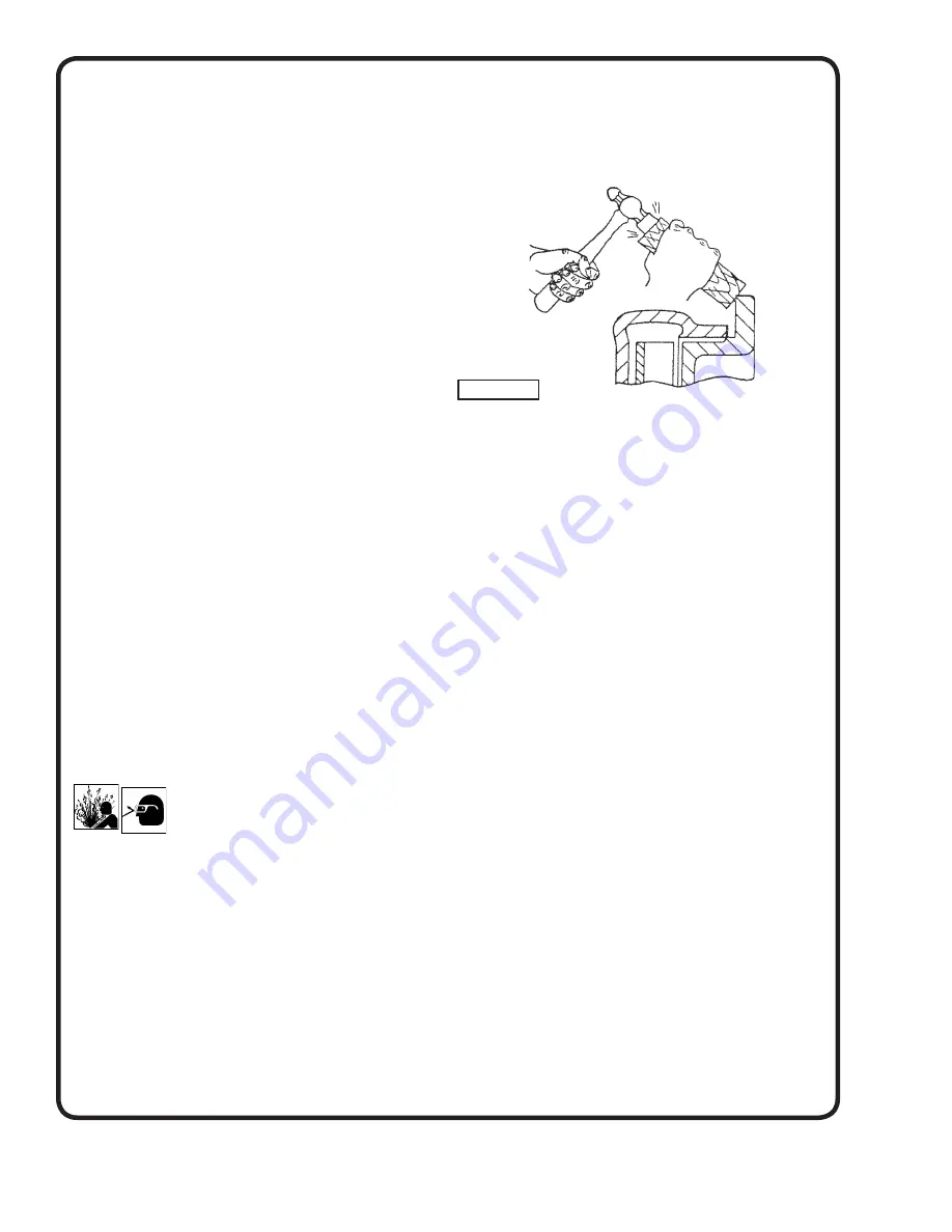
b. Remove suction head capscrews (9), then set a
block of wood against the fi nished fl ange or back
of the suction head (32) and tap block lightly with a
hammer to loosen suction head. Remove suction
head from pump and place suction head gasket (31)
in a bucket of water to keep it soft and pliable.
c. Unscrew the impeller nut (6) by turning counter-
clockwise while holding shaft with a wrench at
slinger (7). Then slide the impeller nut gasket (13) off
the shaft. Place gasket in water.
d. To remove the impeller (40) from the shaft, make
3 special capscrews 1/2” x 13 N.C. with thread
cut 3” long. Screw these capscrews into the three
tapped holes in the impeller shroud. The capscrews
will tighten against the stuffi ng box head (15) thus
forcing the impeller from the shaft. Lift the key (4)
from its seat in the shaft and remove shaft sleeve
gasket (12).
e. To remove the pump casing (35), fi rst disconnect by-
pass tube (21) from the casing then remove casing
capscrews (2), casing and stuffi ng box gasket (14)
will lift off the motor support (1). Place gasket in
water.
f. The stuffi ng box head (15) can be removed after
removing gland (17) bolts and nuts (18) and tubing
(21). Stuffi ng box packing (20), lantern ring (19) and
gland can now be removed.
g. Shaft sleeve (3) and slinger (7) may be removed
from the shaft. If necessary to remove the motor
support (1) remove the motor capscrews (8) and lift
motor support from motor.
h. When necessary to replace wearing rings (36) &
(33), the casing wearing ring (36) can be pressed
from the casing, however it will be necessary to
either machine or cut the suction head wearing ring
(33) from its seat in the suction head.
i. Clean and carefully inspect all parts for wear or
damage. Replace any part which is excessively worn
or damaged.
Figure 3


