background image

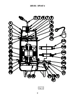
SERIES: SPRINT III

Fig. 18

26

Содержание Barnes SPRINT II Series

Страница 1: ...pump As a result of Crane Pumps Systems Inc constant product improvement program product changes may occur As such Crane Pumps Systems Inc reserves the right to change product without prior written notification 420 Third Street P O Box 603 83 West Drive Brampton Piqua Ohio 45356 0603 Ontario Canada L6T 2J6 Phone 937 778 8947 Phone 905 457 6223 Fax 937 773 7157 Fax 905 457 2650 www cranepumps com P...

Страница 2: ...SPRINT II SERIES EXPLODED VIEW Fig 16 22 SPRINT II SERIES PARTS LIST 23 24 SPRINT III SERIES CROSS SECTION Fig 17 25 SPRINT III SERIES EXPLODED VIEW Fig 18 26 SPRINT III SERIES PARTS LIST 27 WARRANTY INFORMATION 29 WARRANTY START UP REPORT WARRANTY REGISTRATION SPECIAL TOOLS AND EQUIPMENT INSULATION TESTER MEGGER DIELECTRIC TESTER SEAL TOOL KIT see parts list PRESSURE GAUGE KIT see parts list Othe...

Страница 3: ...re on any pump and on end suction and self priming pump the heat build may cause the generation of steam with resulting dangerous pressures It is recommended that a high case temperature switch or pressure relief valve be installed on the pump body ELECTRICAL 21 To reduce risk of electrical shock pump must be properly grounded in accordance with the National Electric Code NEC or Canadian Electrica...

Страница 4: ... Overload Protection In Motor THREE PHASE Dual Voltage 230 460 Requires Overload Protection to be Included in Control Panel FLOAT Automatic Models 15ft Cable Wide Angle Mercury Polypropylene Attached to Pump or to Discharge Piping ON OFF Points Are Adjustable OPTIONAL EQUIPMENT Additional Cable Specify Flange Size and type when ordering IMPORTANT 1 PUMP MAY BE OPERATED DRY FOR EXTENDED PERIODS WIT...

Страница 5: ...e with Current Relay Includes Overload Protection In Motor THREE PHASE Dual Voltage 230 460 Requires Overload Protection to be Included in Control Panel FLOAT Automatic Models 15ft Cable with Plug High Temperature Mechanical Polypropylene Attached To Pump or To Discharge Piping OPTIONAL EQUIPMENT Additional Cable Specify Flange Size and type when ordering inches mm IMPORTANT 1 PUMP MAY BE OPERATED...

Страница 6: ...30 460 Requires Overload Protection to be Included in Control Panel FLOAT Automatic Models 15ft Cable Wide Angle Polypropylene Attached to Pump or to Discharge Piping ON and OFF Points Are Adjustable OPTIONAL EQUIPMENT Additional Cable Specify Flange Size and type when ordering 2 Discharge handels 1 7 8 soilds 3 Discharge handles 2 solids IMPORTANT 1 PUMP MAY BE OPERATED DRY FOR EXTENDED PERIODS W...

Страница 7: ...d Protection In Motor THREE PHASE Dual Voltage 230 460 Requires Overload Protection to be Included in Control Panel FLOAT Automatic Models 15ft Cable Wide Angle Polypropylene Attached to Pump or to Discharge Piping ON and OFF Points Are Adjustable OPTIONAL EQUIPMENT Additional Cable Specify Flange Size and type when ordering 2 Discharge handels 1 7 8 soilds 3 Discharge handles 2 solids inches mm I...

Страница 8: ... under water for more than one 1 month 2 Immediately upon satisfactory completion of the test the pump is removed thoroughly dried repacked in the original shipping container and placed in a temperature controlled storage area B 4 Service Centers For the location of the nearest Barnes Pumps Service Center check your Barnes Engineered catalog your Barnes Pumps Inc representative or Barnes Pumps Inc...

Страница 9: ...nd 5 5 inches on SPRINT III Series above the pump bottom 6 Figure 3 shows a typical connection for pumps with the wide angle float and piggy back plug for manual and automatic operations Automatic Plug float cord into outlet then plug pump cord into float cord Manual Plug pump cord directly into outlet The receptacle must be a three pin polarized type with an internal ground If existing receptacle...

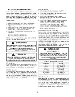
Страница 10: ...PERATION D 1 Check Voltage and Phase Before operating pump check to make sure that the voltage and phase information stamped on the pump s identification plate matches the available power D 2 Check Pump Rotation Before putting pump into service for the first time the motor rotation must be checked Improper motor rotation can result in poor pump performance and can damage the motor and or pump 1 To...

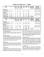
Страница 11: ...T II 1052L 1 0 575 3 M 1 8 10 0 16 4 SO 0 425 38 8 34 5 Mercury Switch on 115 volt and Mechanical on 230 volt SPRINT IIA Cable 16 2 SJOW A 0 320 O D Piggy Back MODEL NO HP VOLT PH NEMA START CODE FULL LOAD AMPS LOCKED ROTOR AMPS CORD SIZE CORD TYPE CORD O D WINDING RESISTANCE PER PHASE WINDING RESISTANCE MAIN START BL Y Y R AUTOMATIC SPRINT IIA 512HT 0 5 115 1 M 12 0 46 0 16 3 STOO 0 390 1 15 1 04...

Страница 12: ...pleted as applicable Return one copy to Barnes Pumps and store the second in the control panel or with the pump manual if no control panel is used It is important to record this data at initial start up since it will be useful to compare to when servicing the pump in the future Insulation Test Before the pump is put into service an insulation megger test should be performed on it The ohm values as...

Страница 13: ...Fig 4 CONNECTION DIAGRAMS USED FOR DETERMINING WINDING RESISTANCE 13 ...

Страница 14: ...for contamination using an oil tester with a range to 30 kilovolts breakdown 3 If oil is found to be clean and uncontaminated measures above 15 KV breakdown refill the motor housing as per section F 1 3 4 If oil is found to be dirty or contaminated or measures below 15KV breakdown then the pump must be carefully inspected for leaks at the shaft seal 30 cord inlet 5 o rings 9 28 and pipe plug 11 be...

Страница 15: ... 2 and install in pump cover 1 F 2 Assembly F 2 1Retaining Ring Install retaining ring 25 on shaft using care so shaft seal mounting surfaces are not nicked or scratched F 2 2 Seal Seat Place drive end bell 29 with seal side up on end bell locating tool Fig 6 on arbor press Apply small amount of light oil to outside of Buna N part of seal seat Set squarely over seal seat recess in end bell with ce...

Страница 16: ...D 4 assemble motor to end bell 29 with 4 motor bolts Place Tetraseal 28 in groove in end bell 29 and lower shell 13 over motor while feeding leads out terminal block opening and bolt to end bell with screws 12 Place o ring 16 over motor leads and make connectiond as shown in Figs 10 thru 14 Secure terminal block 15 with 4 round head screws 14 Conduct motor air check per Section F 1 4 and fill with...

Страница 17: ...Fig 10 SINGLE PHASE 5HP 115 208 OR 230 VOLT 1750 OR 3450 RPM Fig 11 SINGLE PHASE 1HP 208 OR 230 VOLT 3450 RPM Fig 12 THREE PHASE 1HP 208 OR 575V 3450 RPM 5HP 208 OR 575V 1750 OR 3450 RPM 17 ...

Страница 18: ...Fig 13 THREE PHASE 1HP 230V 3450 RPM 5HP 230V 1750 OR 3450 RPM Fig 14 THREE PHASE 1HP 460V 3450 RPM 5HP 460V 1750 OR 3450 RPM 18 ...

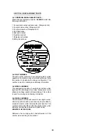
Страница 19: ...ign configuration This number is used for ordering and obtaining information G 3 MODEL NUMBER This designation consists of numbers and letters which represent the discharge size series horsepower motor phase and voltage speed and pump design This number is used for ordering and obtaining information G 4 SERIAL NUMBER The serial number block will consist of a six digit number which is specific to e...

Страница 20: ...Clean impeller cavity and inlet of any obstruction 9 Loosen union slightly to allow trappedair to escape Verify that turn off level of switch is set so that impeller cavity is always flooded Clean vent hole 10 Check rotation If power supply is three phase reverse any two of three power supply leads to ensure proper impeller rotation 11 Repair fixtures as required to eliminate leakage 12 Check pump...

Страница 21: ...Fig 15 SERIES SPRINT II 21 ...

Страница 22: ...Fig 16 SERIES SPRINT II 22 ...

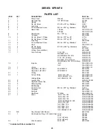
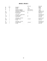
Страница 23: ... 00120 18 1 Impeller 5HP 016 00001 802 1HP 016 00001 801 19 1 Volute 016 00003 101 20 1 Capacitor 1HP 208V 220V 53MFD 625 02744 Capacitor 1HP 230V 220V 40MFD 625 02653 21 1 O Ring 625 01557 22 1 Current Relay 5HP 115V 1Ph 625 02643 001 5HP 208 230V 1Ph 625 02651 001 Voltage Relay 1HP 208 230V 1Ph 625 02652 23 2 Jumper Wire N016 00127 001 24 2 Capacitor Mount Clip 016 00008 25 2 Retaining Ring 625 ...

Страница 24: ...90110 100 40A Discharge Flange 2 016 90110 100 40B 1 Flange Gasket 2 625 02637 41 1 Flange Assy 3 Compression N016 90109 100 41A 1 Discharge Flange 3 016 90109 100 41B 1 Flange Gasket 3 625 02638 42 1 Flange Assy 1 50 NPT N016 00111 101 42A 1 Discharge Flange 1 50 NPT 016 00111 101 42B 1 O Ring 625 01551 43 1 Flange Assy 2 00 NPT N016 00106 101 43A 1 Discharge Flange 1 50 NPT 016 00106 101 43B 1 O...

Страница 25: ...SERIES SPRINT III Fig 17 25 ...

Страница 26: ...SERIES SPRINT III Fig 18 26 ...

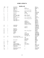
Страница 27: ...x 016 00050 101 19 1 Volute Vortex 016 00051 101 22 1 Current Relay 115V 1Ph 625 02641 001 208V 1Ph 625 02651 001 230V 1Ph 625 02650 001 23 2 Jumper Wire N016 00127 001 25 2 Retaining Ring 625 02579 26 1 Ball Bearing 625 02639 27 4 Fil Hd Screw 8 32 x 875 Lg Stainless 10 97 1 28 1 Tetraseal 625 00042 29 1 End Bell 016 00052 101 30 1 Shaft Seal TP CE B 625 02635 001 31 1 Motor 5HP 115V 1Ph N016 026...

Страница 28: ...NOTES 28 ...

Страница 29: ...of the warranty contact your local Crane Pumps Systems Inc Distributor RETURNED GOODS RETURN OF MERCHANDISE REQUIRES A RETURNED GOODS AUTHORIZATION CONTACT YOUR LOCAL CRANE PUMPS SYSTEMS INC DISTRIBUTOR Products Returned Must Be Cleaned Sanitized Or Decontaminated As Necessary Prior To Shipment To Insure That Employees Will Not Be Exposed To Health Hazards In Handling Said Material All Applicable ...

Страница 30: ...ield performance Any additional guarantees in the nature of performance specifications must be in writing and such writing must be signed by our authorized representative Due to inaccuracies in field testing if a conflict arises between the results of field testing conducted by or for user and laboratory tests corrected for field performance the latter shall control Components or accessories suppl...

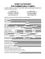
Страница 31: ...bottom Does Impeller Turn Freely By Hand YES NO Condition Of Equipment GOOD FAIR POOR Condition Of Cable Jacket GOOD FAIR POOR Resistance of Cable Jacket GOOD FAIR POOR Resistance of Cable and Pump Motor measured at pump control Red Black Ohms Red White Ohms White Black Ohms Resistance Of Ground Circuit Between Control Panel and Outside of Pump Ohms MEG Ohms Check of Insulation Red to Ground White...

Страница 32: ...n Pump Off L1 L2 L2 L3 L3 L1 Voltage supply at panel line connection Pump On L1 L2 L2 L3 L3 L1 Amperage Load connection Pump On L1 L2 L3 FINAL CHECK Is pump seated on discharge properly Check for leaks Does check valves operate properly Flow Does station appear to operate at proper rate Pump down time Noise Level High Medium Low Comments Equipment Difficulties during start up MANUALS Has operator ...

Страница 33: ...ERIAL NO PART NO BRAND FOLD HERE IMPORTANT WARRANTY REGISTRATION Your product is covered by the enclosed Warranty Complete the Warranty Registration Form and returned to Crane Pumps Systems Inc Warranty Service Group IMPORTANT If you have a claim under the provision of the warranty contact your local Crane Pumps Systems Inc Distributor ...

Страница 34: ...CRANE PUMPS SYSTEMS INC WARRANTY SERVICE GROUP 420 THIRD STREET P O BOX 603 PIQUA OHIO 45356 0603 U S A PLACE STAMP HERE FOLD HERE AND TAPE DO NOT STAPLE ...

Отзывы: