background image

65

busque el período de duración de emisiones importantes yla información de clasificación de aire en 

la etiqueta de emisiones de su motor

Los motores cuyo cumplimiento con los estándares de emisión Tier 2 de la Comisión de Recursos Ambientales de California (CARB) 
esté certificado deben exhibir la información relacionada con el período de duración de las emisiones y la clasificación de aire. Sears, 
Roebuck and Co., de los Estados Unidos ponen esta información a disposición del consumidor en nuestras etiquetas de emisiones.
El Período de Duración de las Emisiones describe el número de horas de tiempo real de funcionamiento para el cual se certifica que 
el motor cumple con las reglas de emisión, descontando el mantenimiento adecuado del mismo según las instrucciones de oper-
ación y mantenimiento. Se utilizan las siguientes categorías:

Moderado:

Se certifica que el motor cumple con las reglas de emisión durante 125 horas de tiempo real de funcionamiento del motor .

Inmediato:

Se certifica que el motor cumple con las reglas de emisión durante 250 horas de tiempo real de funcionamiento del motor .

Extendido:

Se certifica que el motor cumple con las reglas de emisión durante 500 horas de tiempo real de funcionamiento del motor .

Por ejemplo, una cortadora de césped típica que se empuja desde atrás se usa entre 20 y 25 horas por año. Por lo tanto, el 

 Período

de Duración de Emisiones

 de un motor con una  

clasificación

 intermedia sería equivalente a entre 10 y 12 años.

La

clasificación de aire

 es un número calculado para describir el nivel relativo de emisiones para un grupo de motores en particular. 

Cuanto menor sea la 

clasificación de aire

, mayor es la limpieza del motor. La información se presenta de forma gráfica en la etiqueta 

de emisiones.

después del 1 de julio de 2000, busque el período de cumplimiento de las reglas de 

emisiones en la etiqueta de cumplimiento de las reglas de emisiones del motor

Después del 1 de julio de 2000 se certificará que determinados motores Sears, Roebuck and Co., de los Estados Unidos 
cumplen con los estándares de emisiones de la fase 2 de la Agencia de Protección Ambiental de los Estados Unidos (USE-
PA). Para los motores certificados para la etapa 2, el período de cumplimiento con las reglas de emisiones al cual se hace 
referencia en la etiqueta de cumplimiento con las reglas de emisiones indica el número de horas de funcionamiento para el 
cual se ha demostrado que el motor cumple con los requerimientos federales de emisión.
Para los motores con desplazamiento inferior a 225 cc, Categoría C = 125 horas, B = 250 horas y A = 500 horas. 
Para los motores con desplazamiento de 225 cc  o más, Categoría C = 250 horas, B = 500 horas y A = 1000 horas.
El desplazamiento de los motores de la serie modelo 150112 es 249 cc.

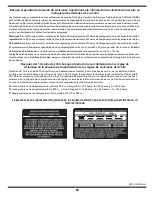
La presente es una representación genérica de la etiqueta de emisión que se encuentra generalmente en un 

motor certificado.

GDOC-100182 Rev. A

Содержание 247.88955

Страница 1: ...bsite www craftsman com CAUTION Before using this product read this manual and follow all safety rules and operating instructions Operator s Manual 24 SNOW THROWER Model No 247 88955 SAFETY ASSEMBLY OPERATION MAINTENANCE PARTS LIST ESPAÑOL 6 3 2008 FORM NO 769 03972 ...

Страница 2: ...ay for Expendable items that become worn during normal use including but not limited to skid shoes shave plate shear pins spark plug air cleaner belts and oil filter Standard maintenance servicing oil changes or tune ups Tire replacement or repair caused by punctures from outside objects such as nails thorns stumps or glass Tire or wheel replacement or repair resulting from normal wear accident or...

Страница 3: ...t operate without wearing adequate winter outer garments Do not wear jewelry long scarves or other loose clothing which could become entangled in moving parts Wear footwear which will improve footing on slippery surfaces Use a grounded three wire extension cord and receptacle for all machines with electric start engines Adjust collector housing height to clear gravel or crushed rock surfaces Disen...

Страница 4: ...nd working Never run an engine indoors or in a poorly ventilated area Engine exhaust contains carbon monoxide an odorless and deadly gas Do not operate machine while under the influence of alcohol or drugs Muffler and engine become hot and can cause a burn Do not touch Keep children away Exercise extreme caution when operating on or crossing gravel surfaces Stay alert for hidden hazards or traffic...

Страница 5: ...season storage Check fuel line tank cap and fittings frequently for cracks or leaks Replace if necessary Do not crank engine with spark plug removed According to the Consumer Products Safety Commission CPSC and the U S Environmental Protection Agency EPA this product has an Average Useful Life of seven 7 years or 60 hours of operation At the end of the Average Useful Life have the machine inspecte...

Страница 6: ...ADES Keep hands out of inlet and discharge openings while machine is running There are rotating blades inside WARNING ROTATING AUGER Do not put hands or feet near rotating parts in the auger impeller housing or chute assembly Contact with the rotating parts can amputate hands and feet WARNING THROWN OBJECTS This machine may pick up and throw and objects which can cause serious personal injury WARN...

Страница 7: ...G MACHINE TO AVOID THROWN OBJECTS INJURIES NEVER DIRECT DISCHARGE AT BYSTANDERS USE EXTRA CAUTION WHEN OPERATING ON GRAVEL SURFACES READ OPERATOR S MANUAL 1 2 3 4 5 DANGER CLEAN OUT TOOL DANGER aVoid injUry from rotating aUger keeP Hands feet and CLotHing aWay DANGER NEVER PUT HAND IN CHUTE CONTACT WITH ROTATING PARTS CAN AMPUTATE FINGERS AND HANDS SHUT OFF ENGINE AND WAIT UNTIL AL L MOVING PARTS ...

Страница 8: ...auger shear pins are included with this manual Refer to Replacing Shear Pins in the Operation section for more information regarding shear pin replacement assembly Place the shift lever in the Forward 6 position 1 Observe the lower rear area of the snow thrower to be sure both 2 cables are aligned with roller guides before pivoting the handle upward See Figure 1 NOTE Make certain the upper ends of...

Страница 9: ... into place use the palm of your hand to apply swift firm pressure to the back of each 6 a Remove the flat washer and hairpin clip from the end of the chute directional control b Insert the end of the chute directional control into the lower bracket and secure with the flat washer and hairpin clip just removed See Figure 5 If necessary the lower bracket can be adjusted Refer to Chute Bracket Adjus...

Страница 10: ...n the auger housing Use a middle or lower position when the area to be cleared is uneven such as a gravel driveway NOTE If you choose to operate the snow thrower on a gravel surface keep the skid shoes in position for maximum clearance between the ground and the shave plate To adjust the skid shoes Loosen the four hex nuts two on each side and carriage bolts 1 Move skid shoes to desired position S...

Страница 11: ...remain engaged for approximately ten 10 4 seconds before releasing the auger control Repeat this several times With the auger control in the disengaged up position walk to the 5 front of the machine Confirm that the auger has completely stopped rotating and 6 shows NO signs of motion If the auger shows ANY signs of rotating immediately return to the operator s position and shut off the engine Wait...

Страница 12: ...e to start Remove the ignition key when the snow thrower is not in use NOTE Do not turn the ignition key in an attempt to start the engine Doing so may cause it to break Choke Control The choke control is found on the rear of the engine and is activated by turning the rotary choke knob to the ON position Activating the choke control closes the choke plate on the carburetor and aids in starting the...

Страница 13: ... the chute assembly Auger Control The auger control is located on the left handle Squeeze the control grip against the handle to engage the augers and start snow throwing action Release to stop Drive Control Auger Control Lock The drive control is located on the right handle Squeeze the control grip against the handle to engage the wheel drive Release to stop Release both controls to stop the auge...

Страница 14: ...tool to the mounting clip on the rear of 5 the auger housing reinsert the ignition key and start the snow thrower s engine While standing in the operator s position behind the snow 6 thrower engage the auger control for a few seconds to clear any remaining snow and ice from the chute assembly Before Starting Engine Oil The unit was shipped with oil in the engine Check oil level before each operati...

Страница 15: ...es before stopping to help dry off any moisture on the engine Move throttle control to STOP 1 position Remove the ignition key Removing the key will reduce the pos 2 sibility of unauthorized starting of the engine while equipment is not in use Keep the key in a safe place The engine cannot start without the ignition key Wipe any moisture away from the controls on the engine 3 To Engage Drive With ...

Страница 16: ...til the fuel tank is empty 1 Be sure fuel fill cap is secure Place suitable oil collection container under oil drain plug 2 Remove oil drain plug See Figure 13 3 Tip engine to drain oil into the container Used oil must be 4 disposed of at a proper collection center Reinstall the drain plug and tighten it securely 5 Refill with the recommended oil and check the oil level 6 See Recommended Oil Usage...

Страница 17: ...einstalling a used spark plug tighten 1 8 to 1 4 turn after the spark plug seats to compress the washer Lubrication Gear Shaft The gear hex shaft should be lubricated at least once a season or after every 25 hours of operation To prevent spillage remove all fuel from tank by running engine 1 until it stops Carefully pivot the snow thrower up and forward so that it rests on 2 the auger housing Remo...

Страница 18: ...to the inside of housing Tighten securely See Figure 18 Adjustments Shift Cable If the full range of speeds forward and reverse cannot be achieved refer to the figure to the right and adjust the shift cable as follows Place the shift lever in the 1 fastest forward speed position F6 Loosen the hex nut on the shift cable index bracket See Figure 2 19 Pivot the bracket downward to take up slack in th...

Страница 19: ...t can be adjusted To do so Loosen the two nuts which secure the chute bracket and reposi 1 tion it slightly See Figure 21 Retighten the nuts 2 Auger Control Refer to the Assembly section for instructions on adjusting the auger control cable Skid Shoes Refer to the Assembly section for instructions on adjusting the skid shoes Belt Replacement Auger Belt To remove and replace your snow thrower s aug...

Страница 20: ...n 4 the auger housing Remove the frame cover from the underside of the snow thrower 5 by removing four self tapping screws which secure it See Figure 24 Remove the belt as follows Refer to Figure 25 6 a Loosen and remove the shoulder screw which acts as a belt keeper b Unhook the support bracket spring from the frame Figure 24 Figure 25 A B Figure 23 ...

Страница 21: ...remov 2 ing the two self tapping screws See Figure 22 on previous page Remove the belt as follows Refer to Figure 27 3 a Roll the auger belt off the engine pulley b Use a wrench to pivot the idler pulley toward the right c Lift the drive belt off engine pulley 4 Carefully pivot the snow thrower up and forward so that it rests on the auger housing 5 Remove the frame cover from the underside of the ...

Страница 22: ...wer up and forward so that it rests on 3 the auger housing Remove the frame cover from the underside of the snow thrower 4 by removing four self tapping screws which secure it Remove the right hand wheel by removing the screw and bell 5 washer which secure it to the axle See Figure 29 Carefully remove the hex nut and washer which secures the hex 6 shaft to the snow thrower frame and lightly tap th...

Страница 23: ...olumn to keep track of completed maintenance tasks To locate the nearest Sears Service Center or to schedule service simply contact Sears at 1 800 4 MY HOME MAINTENANCE SCHEDULE NOTE If you re replacing the friction wheel assembly as a whole discard the worn part and slide the new part onto the hex shaft Follow the steps above in reverse order to reassemble components If you re disassembling the f...

Страница 24: ...r clothes dryer Avoid any area with a spark producing electric motor or where power tools are operated If possible avoid storage areas with high humidity Keep the engine level in storage Tilting can cause fuel or oil leakage If the snow thrower will not be used for 30 days or longer or if it is the end of the snow season when the last possibility of snow is gone the equipment needs to be stored pr...

Страница 25: ...er Spark plug wire loose 1 Gas cap vent hole plugged 2 Connect and tighten spark plug wire 1 Remove ice and snow from gas cap Be certain vent 2 hole is clear Unit fails to propel itself Drive cable in need of adjustment 1 Drive belt loose or damaged 2 Worn friction wheel 3 Adjust drive control cable Refer to Service and 1 Maintenance section Replace drive belt Refer to Service and Mainte 2 nance s...

Страница 26: ...raftsman Snow Thrower Model 247 88955 9 19 55 36 7 50 39 53 46 30 41 44 47 40 49 15 20 45 3 26 24 9 28 5 56 8 12 23 7 14 17 1 18 52 48 54 51 38 43 31 33 35 2 7 9 4 4 34 33 31 21 33 29 16 25 13 5 33 10 32 22 42 37 6 11 ...

Страница 27: ...dler 2 75 OD 25 790 00075 Housing Bearing 1 85 ID 26 790 00080A Bracket Auger Idler w Brake 27 618 04171A Gearbox Assembly Auger 24 28 684 04265 Housing Assembly Auger 24 Ref No Part No Description 29 684 04107 Spiral Assembly LH 30 684 04108 Spiral Assembly RH 31 731 04870 Spacer 1 25 OD x 75 ID x 1 00 32 736 0188 Washer Flat 76 x 1 49 x 06 33 741 0493A Bushing Flange 80 ID x 91 OD 34 790 00087A ...

Страница 28: ...28 PARTS LIST Craftsman Snow Thrower Model 247 88955 16 24 25 6 31 9 28 7 12 6 8 44 19 12 4 3 32 37 12 36 11 38 30 17 15 10 13 33 39 34 12 35 27 41 26 23 29 40 21 18 22 20 14 20 43 42 15 1 5 ...

Страница 29: ...5 16 18 Black 21 720 0201A Crank Knob 1 0 Dia x 3 2 Black 22 749 04138A Handle Lower Ref No Part No Description 23 735 0199A Bumper Rubber 62 OD x 22 24 736 0262 Washer Flat 385 x 870 x 092 25 738 04118 Bolt Shoulder 5 16 18 x 0 905 26 738 04348 Screw Shoulder 43 x 1 3 1 4 20 27 731 04869 Chute Flange Keeper 28 746 04397 Cable Speed Selector 29 749 04191A Handle Upper LH 30 747 04263 Eye Bolt Chut...

Страница 30: ...5 53 22 21 50 62 42 63 40 33 30 24 36 18 5 25 37 19 6 31 7 30 24 26 13 23 47 44 23 43 39 2 7 5 34 24 30 51 58 52 61 35 27 7 14 55 48 46 7 59 59 49 41 2 1 11 4 A B B A 8 26 16 28 45 29 17 3 9 54 32 60 57 56 60 20 10 15 12 38 65 64 68 67 72 71 66 23 69 70 ...

Страница 31: ... Cover Frame 36 634 04167A LH Wheel Assembly 634 04168A RH Wheel Assembly Ref No Part No Description 37 731 04873 Spacer 1 25 x 75 x 3 0 38 738 04168 Axle 75 x 22 39 729 04035 Conn Amp 40 710 0809 Hex Screw 1 4 20 1 25 Gr5 41 710 0191 Hex Screw 3 8 24 1 25 Gr8 42 710 0672 Hex Screw 5 16 24 1 25 Gr5 43 710 0654A Screw Sems 3 8 16 1 00 44 710 1245B Hex Screw 5 16 24 875 Gr8 45 710 0896 Screw 1 4 20 ...

Страница 32: ...32 PARTS LIST Craftsman Engine Model ZS365 SUA For Snow Thrower Model 247 88955 ...

Страница 33: ...A 752Z365 Engine Complete N A SUA 751 10719 Stator 28 751 10911 Starter Cup 32 751 10909 Cooling Fan 31 751 10805 Flywheel 30 751 10757 Throttle Control Knob 82 751 10758 Throttle Control Assembly 81 Part No Description Ref No 751 10723 Gasket Kit Complete Oil Seal 4 Crankcase Cover Gasket 10 O Ring 15 Oil Seal 21 Cylinder Head Gasket 55 Muffler Gasket 59 Valve Cover Gasket 47 Carburetor Insulator...

Страница 34: ...adial Ball Bearing 13 Bolt 1 Oil Seal 4 O Ring Governor Arm 15 Oil Filler Plug 2 O Ring Oil Filler Plug 3 Oil Drain Pipe 18 Radial Ball Bearing 6 Oil Seal 21 Part No Description Ref No 751 10641 Oil Drain Assembly Oil Drain Pipe 18 Drain Bolt 20 751 10647 Valve Kit Exhaust Valve 98 Intake Valve 103 751 10648 Push Rod Kit Push Rod 97 751 10649 Fuel Cap Assembly Fuel Cap Complete 111 Packing Gasket ...

Страница 35: ...l Emissions Warranty Coverage MTD must warrant to the ultimate purchaser and each subsequent purchaser that the engine is 1 Designed built and equipped so as to conform with all applicable regulations adopted by the Air Resources Board pursuant to its authority in Chapters 1 and 2 Part 5 Division 26 of the Health and Safety Code and 2 Free from defects in materials and workmanship that cause the f...

Страница 36: ... any non exempted add on or modified parts shall be grounds for disallowing a warranty claim made in accordance with this article The engine manufacturer shall not be liable under this article to warrant failures of warranted parts caused by the use of non exempted add on or modified part c MTD will include a copy of the following emission warranty parts list with each new engine using those porti...

Страница 37: ...typical walk behind lawn mower is used 20 to 25 hours per year Therefore the Emissions Durability Period of an engine with an intermediate rating would equate to 10 to 12 years The Air Index is a calculated number describing the relative level of emissions for a specific engine family The lower the Air Index the cleaner the engine This information is displayed in graphical form on the emissions la...

Страница 38: ...one we call it Rapid Resolution phone support from a Sears representative Think of us as a talking owner s manual Once you purchase the Agreement a simple phone call is all that it takes for you to schedule service You can call anytime day or night or schedule a service appointment online The Repair Protection Agreement is a risk free purchase If you cancel for any reason during the product warran...

Страница 39: ...a por pinchazos desde fuera de objetos como uñas espinas tocones o cristal Neumático o reemplazo de rueda o reparación que resulta de ropa normal accidente u operación impropia o mantenimiento Las reparaciones necesarias debido al abuso de operador incluso pero no limitado para dañar causado afectando objetos que doblan el marco o el cigüeñal o el sobreexceso de velocidad del motor Reparaciones ne...

Страница 40: ...ta adecuada para estar al aire libre en invierno No utilice alhajas bufandas largas u otras prendas sueltas que podrían enredarse en las partes móviles Utilice un calzado especial para superficies resbaladizas Use un prolongador y un tomacorriente de tres cables con conexión a tierra para todas las máquinas con motores de encendido eléctrico Ajuste la altura de la caja del tomacorriente para limpi...

Страница 41: ...as direc ciones y regresar automáticamente a la posición de desengrane cuando se las suelta Nunca opere la máquina si falta un montaje del canal o si el mismo está dañado Mantenga todos los dispositivos de seguri dad en su lugar y en funcionamiento Nunca encienda el motor en espacios cerrados o en una zona con poca ventilación El escape del motor contiene monóxido de carbono un gas inodoro y letal...

Страница 42: ...í que se congele la barrena impulsor Según la Comisión de Seguridad de Productos para el Consu midor de los Estados Unidos CPSC y la Agencia de Protección Ambiental de los Estados Unidos EPA este producto tiene una vida útil media de siete 7 años ó 60 horas de funcionamiento Al finalizar la vida útil media adquiera una máquina nueva o haga inspeccionar anualmente ésta por un distribuidor de servic...

Страница 43: ...IVAS Guarde manos de entrada y aperturas de descarga mientras la máquina corre Allí hacen girar láminas dentro LA ADVERTENCIA TALADRO ROTATIVO No ponga manos o pies cerca del giro de partes en el alojamiento de taladro aspa o asamblea de tolva Contacto con las partes rotativas puede amputar manos y pies OBJETOS LANZADOS POR ADVERTENCIA Esta máquina puede recoger y lanzar y objetos que pueden causa...

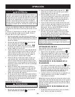
Страница 44: ...e repuesto Consulte la sección Barrenas en la sección de Servicio y Mantenimiento para obtener más información sobre el reemplazo de los pasadores de cuchilla de barrena MOntaje Coloque la palanca de cambios en la posición de avance F 6 1 Observe el área inferior trasera de la máquina quitanieve para 2 asegurarse de que ambos cables estén alineados con las guías rotatorias antes de girar la manija...

Страница 45: ... la palma de su mano para aplicar una presión rápida y firme en la parte posterior de cada uno 6 a Quite la arandela plana y el broche de horquilla del extremo del control direccional del canal b Inserte el extremo del control direccional del canal en el soporte inferior y asegúrelo mediante la arandela plana y el broche de horquilla que acaba de retirar Vea la figura 5 Si es necesario puede ajust...

Страница 46: ...en la caja de la barrena Use las posiciones media o baja cuando la superficie que desee limpiar sea despareja como un camino de grava NOTA Si tiene que usar la máquina quitanieve sobre grava mantenga la zapata antideslizante en la posición más elevada para lograr una separación máxima entre el piso y la placa de raspado Para ajustar las zapatas antideslizantes Afloje las cuatros tuercas hexagonale...

Страница 47: ...ente diez 10 4 segundos antes de soltar el control de la barrena Repita esta operación varias veces Con la barrena en posición desengranada arriba camine al frente 5 de la máquina Confirme que la barrena ha dejado de girar por completo y no 6 muestra NINGÚN signo de movimiento Si la barrena muestra CUALQUIER signo de rotación vuelva a la posición del operador y apague el motor inmediatamente Esper...

Страница 48: ...OTE No gire la llave de encendido para intentar arrancar el motor Al hacerlo podría romperla Control de obturación El control de obturación se encuentra en la parte posterior del motor y se activa haciendo girar el control de obturación a posición ON Al activar el control de obturación se cierra la placa de obturación del carburador y se ayuda a encender el motor Figura 10 Cumple con los estándare...

Страница 49: ...r aceite a través del llenado de aceite Tapón de combustible Desenrosque el tapón de combustible para agregar gasolina al tanque de combustible Zapatas antideslizantes Ubique las zapatas antideslizantes en función de las condiciones de la superficie Ajuste hacia arriba si la nieve está muy compactada Ajústelas hacia abajo si usa la máquina en gravas o superficies con piedras trituradas Control de ...

Страница 50: ...r el motor Gasolina Utilice gasolina para automóviles sin plomo o con bajo contenido de plomo para minimizar los depósitos en la cámara de combustión con un octanaje mínimo de 87 Se puede usar gasolina con hasta un 10 de etanol o un 15 de MTBE éter metílico terciario butílico Nunca use una mezcla de aceite y gasolina ni gasolina sucia Evite que se introduzca suciedad polvo o agua en el tanque de c...

Страница 51: ... Consulte con un electricista matriculado si no está seguro Si cuenta con un receptáculo de tres terminales siga los siguientes pasos Si el cableado de su hogar no es el adecuado NO use el arrancador eléctrico en ninguna circunstancia Conecte el prolongador a la salida situada en la superficie del 1 motor Conecte el otro extremo del prolongador en un receptáculo de CA con conexión a tierra de tres...

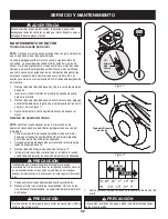
Страница 52: ...or 1 hasta que el tanque de combustible esté vacío Cerciórese de que la tapa del combustible está asegurada Coloque un recipiente adecuado para recolectar el aceite bajo el 2 tapón de drenaje de aceite Retire el tapón de drenaje de aceite Vea la Figura 12 3 Incline el motor para drenar el aceite en el recipiente El aceite 4 usado se debe descartar en un centro de recolección adecuado Vuelva a colo...

Страница 53: ...ía apriete 1 8 1 4 de vuelta para comprimir la arandela Lubricación Eje de engranaje El eje de engranaje hexagonal se debe lubricar al menos una vez por temporada o tras cada 25 horas de operación Para prevenir el derramamiento elimine todo el combustible del 1 tanque haciendo funcionar el motor hasta que se detenga Gire con cuidado la máquina quitanieve hacia arriba y hacia 2 delante de manera qu...

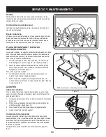
Страница 54: ...lado arandelas y las tuercas de brida hexagonales Consulte la figura 17 Para retirar la placa de raspado Quite los pernos de carro y las tuercas hexagonales que la 1 sujetan a la caja de la máquina quitanieve Monte la placa de raspado nueva asegurándose de que las 2 cabezas de los pernos de carro se encuentren del lado interior de la caja Ajuste bien ajustes Cable de cambios Si no se puede lograr ...

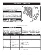
Страница 55: ...ntar la tensión del cable Vuelva a apretar la tuerca hexagonal superior 7 Soporte del canal Si la espiral situada en la parte inferior del control direccional del canal no se engancha completamente con el montaje del canal es posible ajustar el soporte del canal Para hacerlo Afloje las dos tuercas que sujetan el soporte del canal y cambie 1 su posición ligeramente Vea la figura 20 Vuelva a ajustar...

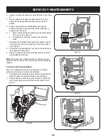
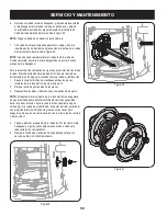
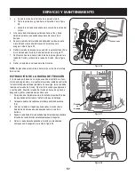
Страница 56: ...rte y la polea de la barrena Vea la figura 25 8 Para realizar el reensamblado de la correa de la barrena siga las instrucciones en orden inverso 9 Realice la prueba de Control de Taladro perfilada en la sección de Asamblea de este manual NOTA NO olvide volver a instalar el tornillo con reborde y volver a conectar el resorte al marco tras instalar una correa de la barrena de repuesto La correa de l...

Страница 57: ...ilita el montaje de la correa Extracción de la rueda de fricción Si la máquina quitanieve no se acciona cuando el control de la trans misión está engranado y si al realizar el ajuste del cable de control de la transmisión que aparece el problema no se corrige tal vez se deba reemplazar la rueda de fricción Siga las instrucciones que aparecen a continuación Examine la rueda de fricción en busca de ...

Страница 58: ... el anillo de goma proceda como se indica a continuación Saque los cuatro tornillos de mantienen unidas las placas 1 laterales de la rueda de fricción Vea la figura 31 Retire el anillo de goma de entre las placas 2 Reensamble las placas laterales con un nuevo anillo de goma 3 NOTA Al reensamblar el conjunto de la rueda de fricción asegúrese de que el anillo de goma esta correctamente centrado y as...

Страница 59: ...ntrol 2 y pivotes Ruedas 3 Eje de engranaje y eje de la 4 barrena Comprobar 1 Lubricación con petróleo ligero 2 Lubricación con 3 automotores multiusos Lubricación con petróleo ligero 4 Anualmente o 50 horas El aceite de motor 1 Cambio 1 Anualmente o 100 horas Bujía 1 Cambio 1 Antes de Almacenaje Sistema de combustible 1 El motor dirigido hasta que esto se 1 pare a falta del combustible Siga la li...

Страница 60: ...icen herramientas eléctricas Si es posible evite sectores de almacenamiento con mucha humedad Mantenga el motor nivelado en el almacén La inclinación del motor puede causar pérdidas de combustible o aceite Preparación de la máquina quitanieve Cuando almacene la máquina quitanieve en un galpón de 1 depósito metálico o con poca ventilación tenga especial cuidado de realizarle un tratamiento anti oxi...

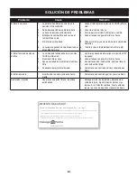
Страница 61: ... necesario ajustar el carburador 4 Cambie la palanca de obturación a la posición OFF 1 apagado Llene el tanque con gasolina limpia y fresca 2 Vacíe el tanque del combustible Vuelva a llenarlo 3 con combustible limpio Contacte con su centro de partes y reparaciones 4 Sears El motor recalienta El carburador no está ajustado correcta 1 mente Contacte con un centro de partes y servicio Sears 1 Demasia...

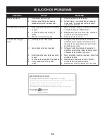
Страница 62: ...del control de la barrena necesita 3 un ajuste La correa de la barrena está floja o dañada 4 El los pasador es de cuchilla están 5 cortados Detenga el motor de inmediato y desconecte el 1 cable de la bujía Limpie el montaje del canal y el interior de la caja de la barrena con la herramienta de limpieza o una varilla Detenga el motor de inmediato y desconecte el 2 cable de la bujía Retire el objeto...

Страница 63: ...e Asistencia al Cliente de Distribuidores de MTD llame al número 800 800 7310 REQUERIMIENTOS DE GARANTÍA SOBRE DEFECTOS PARA MOTORES PEQUEÑOS DE EQUIPO TODO TERRENO DE 1995 Y VERSIONES POSTERIORES Esta sección se aplica a motores pequeños de equipo todo terreno de 1995 y versiones posteriores El período de garantía comienza a partir de la fecha en que el motor o el equipo se entregan al comprador ...

Страница 64: ... o reparaciones bajo garantía y se suministrará sin cargo al propietario Dicho uso no reducirá las obligaciones de garantía de MTD 10 No se podrán usar piezas adicionales ni modificadas que no estén exentas de acuerdo con el Departamento de los Recursos del Aire Air Resources Board El uso de piezas adicionales o modificadas no exentas será causa suficiente para anular un reclamo bajo garantía real...

Страница 65: ...o tanto el Período de Duración de Emisiones de un motor con una clasificación intermedia sería equivalente a entre 10 y 12 años Laclasificación de aire es un número calculado para describir el nivel relativo de emisiones para un grupo de motores en particular Cuanto menor sea la clasificación de aire mayor es la limpieza del motor La información se presenta de forma gráfica en la etiqueta de emisi...

Страница 66: ...no lo llamamos Resolución Rápida el apoyo telefónico de un Chamusca al representante Piense en nosotros como el manual de un dueño hablador Una vez adquirido el Acuerdo puede programar el servicio con tan sólo realizar una llamada telefónica Puede llamar en cualquier momento del día o de la noche o programar un servicio en línea El Acuerdo de Protección de Reparación es una compra sin riesgo Si us...

Страница 67: ...NOTAS 67 ...
Страница 68: ...do it yourself For Sears professional installation of home appliances and items like garage door openers and water heaters 1 800 4 MY HOME 1 800 469 4663 Call anytime day or night U S A and Canada www sears com www sears ca Our Home For repair of carry in items like vacuums lawn equipment and electronics call anytime for the location of your nearest Sears Parts Repair Service Center 1 800 488 1222...

Отзывы: