background image

1017952-A

Page 24

COZY HEATING SYSTEMS, LLC

3230 INDUSTRIAL PARKWAY.  –  JEFFERSONVILLE, IN 47130

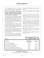
LIMITED WARRANTY

Cozy Heating Systems LLC warrants to the original 

user the accompanying product for the period specified 

herein, provided said product is installed, operated, 

maintained, serviced, and used according to the 

instructions and specifications accompanying the 

product. 

AS  OUTLINED  IN  OUR  INSTRUCTIONS,  ANY 

WARRANTY CONSIDERATIONS ARE CONTINGENT 

ON INSTALLATION BY A QUALIFIED INSTALLER 

(CONTRACTOR). SELF-INSTALLATION IS PROHIBITED 

AND WILL INVALIDATE YOUR WARRANTY.

If within a period of one year from the date of installation 

of the product, any part supplied by the manufacturer 

proves to be defective due to workmanship or material, 

it will replace such part, provided parts have not been 

subjected to misuse, alteration, neglect, or accidents. The 

term of the warranty for the heat exchanger and burners 

is covered in Table A below. Any claim not made within ten 

(10) days after the expiration of the warranty period shall 

be deemed waived by the user. 

The manufacturer shall have no liability or be required 

to perform any obligation under this warranty unless, when 

requested, the user returns, at the user’s expense, the 

component or product claimed defective, to the manufacturer 

for inspection, to enable the manufacturer to determine if the 

claimed defect is covered by this warranty.

No charges for freight, labor or other expenses incurred 

in the repair, removal, or replacement of any product or 

component claimed to be defective, will be paid by the 

manufacturer to the user, and the manufacturer will not be 

liable for any expenses incurred, by the user, in remedying 

any defect in the product.

Service under this warranty is the responsibility of 

the installer. In the event service under this warranty is 

needed, the user of the product shall request such service 

directly from the installer. If the user is unable to locate the 

installer, the user should write directly to the manufacturer, 

and the name of an alternative service source will be 

supplied.

The product safety registration card (packed inside the 

appliance) must be completed and returned to the factory.

_________________________________________________

THIS WARRANTY IS EXPRESSLY IN LIEU OF ANY OTHER 

WARRANTIES, EXPRESS OR IMPLIED (WHETHER 

WRITTEN OR ORAL). ANY IMPLIED WARRANTY OF 

MERCHANTABILITY OR OF FITNESS FOR A PARTICULAR 

PURPOSE IS EXPRESSLY LIMITED TO THE DURATION 

OF THE MANUFACTURER’S EXPRESS, WRITTEN 

WARRANTY.
UNDER NO CIRCUMSTANCES SHALL THE MANUFACTURER 

BE LIABLE FOR ANY SPECIAL, INDIRECT OR 

CONSEQUENTIAL DAMAGES OR EXPENSES ARISING 

DIRECTLY OR INDIRECTLY FROM ANY COMPONENT OR 

FROM THE USE THEREOF. THE REMEDIES SET FORTH 

HEREIN SHALL BE THE EXCLUSIVE REMEDIES AVAILABLE 

TO THE USER AND ARE IN LIEU OF ALL OTHER REMEDIES.
SOME STATES DO NOT ALLOW LIMITATIONS ON HOW 

LONG AN IMPLIED WARRANTY LASTS, SO THE ABOVE 

LIMITATIONS MAY NOT APPLY TO YOU.
SOME STATES DO NOT ALLOW THE EXCLUSION OR 

LIMITATION OF INCIDENTAL OR CONSEQUENTIAL 

DAMAGES, SO THE ABOVE LIMITATIONS OR EXCLUSIONS 

MAY NOT APPLY TO YOU.
THIS WARRANTY GIVES YOU SPECIFIC LEGAL RIGHTS, 

AND YOU MAY ALSO HAVE OTHER RIGHTS, WHICH VARY, 

FROM STATE TO STATE.

Cozy Gas Fired Floor Furnace  

10 Years  

10 Years

Cozy Gas Fired Wall Furnace  

10 Years  

10 Years

Cozy Gas Fired Vented Console Heater  

10 Years  

10 Years

Cozy Gas Fired Direct Vent Heater  

10 Years  

10 Years

Cozy Gas Fired Counterflow Furnace  

10 Years  

10 Years

Cozy Gas Fired Counterflow Direct Vent Furnace  

10 Years  

10 Years

Cozy Gas Fired Hi-Efficient Direct Vent Wall Furnace  

10 Years  

10 Years

Cozy Fan-Type, Direct Vent Through-The-Wall Gas Heater  

10 Years  

10 Years

WARRANTY PERIOD

TUBES / HEAT  

EXCHANGER  

PRODUCT

BURNERS

TABLE - A

Содержание HEDV253A and

Страница 1: ...Suministro de gas en bruto 8 Instalación del sistema de ventilación 9 Instalación del calentador 10 Instrucciones de operación 11 Llama apropiada de la hornilla 12 Limpieza del quemador 12 Gráfico de orificios y orificios del quemador 12 Cableado 13 Secuencia de operaciones 14 Kits HEVK 5 Vent Exhaust 15 Recinto de Ventilación HEVE 5 16 HEEL 1 90º 16 18900 Condensado 17 Instrucciones de Mantenimie...

Страница 2: ...UT THE PROPERLY INSTALLED FACTORY FURNISHED VENT SYSTEM AND VENT CAP COULD RESULT IN CARBON MONOXIDE C O POISONING AND POSSIBLE DEATH FOR YOUR SAFETY THIS FURNACE AND THE VENT SYSTEM SHOULD BE INSPECTED AT LEAST ANNUALLY BY A QUALIFIED SERVICE TECHNICIAN The coating selected to provide longer life to the heat exchanger may smoke slightly upon initial firing Please provide adequate ventilation if t...

Страница 3: ...and ordinances Before planning or making the installation be sure it complies with all phases of the local heating code Or in the absence of local codes with the latest edition of National Fuel Gas Code ANSI Z223 1 or CAN1 B149 The appliance when installed must be electrically grounded in accordance with local codes or in the absence of local codes with the latest edition of National Electrical Co...

Страница 4: ...perty damage bodily injury or death 2 Use in other than a residential application may result in unsatisfactory performance may create unsafe conditions and will invalidate the warranty 3 The installation must conform with local codes or in the absence of local codes wtih the National Fuel Gas Code ANSI Z223 1 NFPA 54 Natural Gas and Propane Installation Code CSA B149 1 4 DO NOT INSTALL THIS FURNAC...

Страница 5: ...oxide poisoning or death The following steps shall be followed for each appliance connected to the venting system being placed into operation while all other appliances connected to the venting system are not in operation USE AND AT LEAST ANNUALLY BY A QUALIFIED SERVICE TECHNICIAN More frequent cleaning may be required due to excessive lint from carpeting bedding material etc It is imperative that...

Страница 6: ...walk or paved driveway located on public property 12 Inches 30 cm 18 Inches 46 cm 12 Inches 30 cm 12 Inches 30 cm 3 Feet 91 cm 12 Inches 30 cm 12 Inches 30 cm 12 Inches 30 cm 6 Feet 1 83 m 3 Feet 91 cm within a height 15 Feet 4 5m above the meter regulator assembly 12 Inches 30 cm Permitted only if veranda porch deck or balcony is fully open on a minimum of two sides 18 Inches 46 cm 7 Feet 2 13m A...

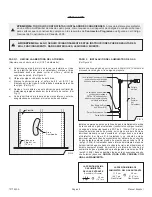
Страница 7: ...ntilation air 8 Clearances listed are minimum Adequate accessibility clearances for servicing must be maintained 9 RESIDENTIAL GARAGE INSTALLATION Gas utilization equipment in residential garages shall be installed so that all burners and burner ignition devices are located not less than 18 inches 46 cm above the floor You must build a platform 18 above floor the full width and depth of the heater...

Страница 8: ...ed in a basement a 12 clearance must be maintained between ground level and the bottom of the vent cap Do not install furnace where vent cap will terminate in a window well or any other opening below ground level See Figure 3 Do not allow snow accumulation to build up within 12 of the vent cap 1 HEVK 5 To extend vent 5 foot from heater This will allow vent cap to be installed above grade from base...

Страница 9: ...3 8 gas supply line Contact local gas supplier if any questions Template Wall Studs 16 O C Shaded Area FIG 5 Manual shut off valve must be accessible in room where heater is installed Manual shut off valve with 1 8 NPT plugged tapping must be accessible in room where heater is installed Gas Valve Gas Supply Drip Leg Wall 3 8 Black Iron Pipe Back of Heater Install a drip leg in gas supply line imme...

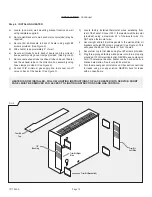
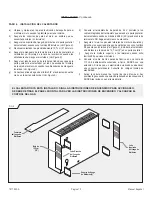
Страница 10: ...tion box pipes and push in until flange is flush against house Secure vent cap assembly to outside wall with a slight downward slope This will prevent water from entering and allow condensation to drain Caulk around the edges of the vent cap mounting plate NOTE It may be necessary to build a metal or wood frame to provide a flat surface for the mounting plate to be flush against or to attain the 5...

Страница 11: ...of the heater Connect 24 V thermostat wall thermostat provided using a maximum 20 of thermostat wire Do NOT splice thermostat wire i Secure right and left trim side panels to the wall and trim kit brackets with eight 8 screws provided See Figure 9 This will space the back of the heater 5 from the wall j Secure trim top to trim sides using four 8 screws provided k Plug three pronged factory wired p...

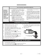
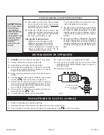
Страница 12: ...d repair may result in a fire or explosion D Do not use this appliance if any part has been under water Immediately call a qualified service technician to inspect the appliance and to replace any part of the control system and any gas control which has been under water WARNING If you do not follow these instructions exactly a fire or explosion may result causing property damage personal injury or ...

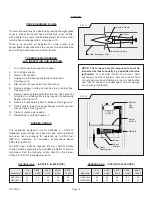
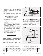
Страница 13: ...e care not to contact or strain ignitor in any way as it is extremely fragile See Figure 12 8 Remove 2 nuts holding burner bracket See Figure 12 9 Slide burners toward heat exchanger and lift up from rear and back See Figure 12 10 Clean or replace as needed 11 Reinstall by reversing Steps 9 1 FIG 11 Primary Flame Secondary Flame Heat Exchanger Tube Burner FIG 12 NOTE The furnace and all components...

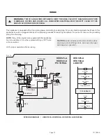
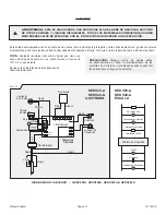
Страница 14: ...an cause improper and dangerous operation WARNING THIS IS A GAS FIRED APPLIANCE KEEP THE AREA CLEAR OF GASOLINE AND OTHER FLAMMABLE VAPORS AND LIQUIDS ALL COMBUSTIBLE MATERIAL MUST BE KEPT CLEAR OF THIS AREA TO AVOID FIRE OR EXPLOSION Verify proper operation after servicing Pressure Switch Black Gas Valve Purple Red White Black Black Black Green Black Circulating Blower Draft Inducer CMB Blower Ci...

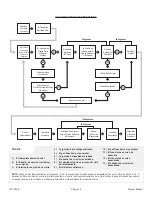
Страница 15: ...for Ignition One Hour Lock Out NOTE If there is a malfunction during Steps 3 5 or 6 the operation sequence will stop at that point For Steps 5 or 6 if the malfunction still occurs after two additional attempts the control will lock out for one hour For purpose of testing the one hour lockout can be overridden by resetting the thermostat or interrupting the electrical power 1 Thermostat calls for h...

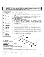
Страница 16: ... Attach P N 72612 2 x6 black flex tubing to air inlet Secure with P N 72593 2 hose clamp 3 3 Slide P N 72575 2 x5 flocked tube through trim kit opening knockout and attach to P N 72610 orange silicone 90E elbow supplied with heater Secure with 2 hose clamp 3 4 Attach P N 41515 support brackets to wall Wall anchors not provided may be required Postion support brackets within 8 from side of trim kit...

Страница 17: ...E 5 Kit Step 2 Cut to fit enclosure panel 1 beyond end of vent run Insert Part No 41620 End Cap and attach using three 8 screws provided SPECIAL INSTRUCTIONS Step 3 If more than one HEVE 5 Kit is used attach Part No 72604 Trim Kit where ends meet Step 4 If making a 90º turn measure 1 beyond outside turn and cut off enclosure panel Notch panel on surface of direction turn is being made to allow pip...

Страница 18: ...move and discard the button plug located at center lower area of heater back Step 8 Attach condensate trap to heater back so bottom of trap is inside the bottom of the condensate pan Secure using the 2 8 screws provided Fill trap with water See Figure 17 Step 9 Remove and discard plastic cap from bottom of the draft inducer drain tube See Figure 17 Step 10 Connect the tubing to the draft inducer d...

Страница 19: ...nd burner operation prior to use each year SERVICE MAINTENANCE Follow a regular service and maintenance schedule for safe and efficient operation DO NOT OBSTRUCT COMBUSTION VENTILATION AIR Examine the venting system as a routine part of the safety performance check on an annual basis REMOVED HEAT EXCHANGER If the heat exchanger is removed check the heat exchanger intake gasket and draft inducer ga...

Страница 20: ...1017952 A Page 19 SERVICE RECORDS ...

Страница 21: ...r gas company can supply you with this information If furnace is undersized replace with correct size unit 2 Raise thermostat temperature setting 3 Check supply pressure 1 Re check gas input 2 Clean orifices with a smooth wood toothpick do not enlarge 1 Defective or damaged thermostat wire or thermostat 2 Thermostat location 3 Defective or sticking valve 4 Excessive gas pressure 5 Defective or dam...

Страница 22: ...Flame Pressure Switch Open or Closed Limit Switch Opens Flame Sensed Gas Valve Not Energized Internal Failure Control module failure and power on self check 2 3 4 5 Steady Light No Flashes Normal Operation NO CALL FOR HEAT Slow Flash Normal Operation CALL FOR HEAT Fast Flash 1 Replace ignitor 2 Replace ignitor cable 3 Connect ignitor cable 4 Turn manual gas valve to ON 5 Replace defective wire 6 C...

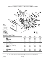
Страница 23: ...72501 72500 72500 3 Limit Switch 72671 72671 72670 72670 4 Front Heat Shield 72531 72531 72530 72530 5 Tubular Heat Exchanger 18120 18120 18620 18620 6 Cabinet Base Assembly 18120 18120 18620 18620 7 Leg Leveler 4 Per 80009 80009 80009 80009 8 Draft Inducer Gasket 7 3 4 x 9 72565 72565 72565 72565 9 Draft Inducer Mounting Plate Gasket 72563 72563 72563 72563 10 Draft Inducer 72506 72506 72506 7250...

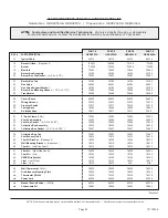
Страница 24: ...ss 72675 72675 72675 72675 28 Pressure Switch 72517 72517 72518 72518 29 Casing Back 18090 18090 18590 18590 30 Air Intake Hose 72611 72611 72611 72611 31 2 Hose Clamp 4 Per 72593 72593 72593 72593 32 Vent Cap Assembly 18250 18250 18650 18650 33 Vent Cap Gasket 4 3 32 x 4 3 32 72608 72608 72608 72608 34 Collection Box Assembly 18225 18225 18225 18225 35 Collection Box Gasket 5 7 16 x 5 7 16 72607 ...

Страница 25: ...ller In the event service under this warranty is needed the user of the product shall request such service directly from the installer If the user is unable to locate the installer the user should write directly to the manufacturer and the name of an alternative service source will be supplied The product safety registration card packed inside the appliance must be completed and returned to the fa...

Страница 26: ...rnaderos o ambientes con condiciones polvorientas mojadas corrosivas o explosivas Tales condiciones invalidarán la garantía y pueden crear condiciones inseguras Este aparato se puede instalar en una casa prefabricada de ubicacion permanente unicamente en los E E U U o donde el codigo local no lo prohiba en una casa movil Este aparato solo se debe usar con el tipo de gas indicado en la placa de dat...

Страница 27: ...l código local sobre calefactores O en ausenciade códigos locales asegúrese de que está en cumplimiento con la última edición del Código Nacional para Gas Combustible ANSI Z223 1 o CAN1 B149 El aparato al ser instalado debe hacer tierra en conformidad con los códigos locales o en ausencia de los códigos locales con la última edición del Código Nacional sobre Electricad ANSI NFPA 70 o el Código Can...

Страница 28: ...el mantenimiento inadecuados puede causar daños materiales lesiones personales o la muerte 2 El uso no residencial de este dispositivo puede ocasionar funcionamiento insatisfactorio condiciones inseguras y la anulación de la garantía 3 La instalación debe cumplir con los códigos locales o en la ausencia de los mismos con el Código Nacional de Gas Combustible ANSI Z223 1 NFPA 54 y el Código de Inst...

Страница 29: ...ntilación que se coloca en funcionamiento podría provocar intoxicación por monóxido de carbono o la muerte Para cada dispositivo conectado al sistema de ventilación que esté siendo puesto en funcionamiento deben seguirse los siguientes pasos mientras los demás dispositivos conectados al sistema de ventilación no estén en funcionamiento 15 LA INSTALACIÓN Y LAS REPARACIONES DEBEN SER LLEVADAS A CABO...

Страница 30: ...ulgadas 91 cm 3 pies 30 cm 12 pulgadas 30 cm 12 pulgadas 30 cm 12 pulgadas 1 83 m 6 pies 91 cm 3 pies Dentro de una altura de 4 5m 15 pies sobre el montaje medidor regulador 30 cm 12 pulgadas Se permite sólo si la baranda porche nivel o balcón es totalmente abierto por lo menos en dos lados 46cm 18 pulgadas 2 13 m 7 pies Una tobera no puede quedar justo sobre una acera o vía pavimentada ubicada en...

Страница 31: ...e la presente lista son el mínimo Se deben mantener distancias de acceso adecuado para llevar a cabo el servicio técnico 9 INSTALACIÓN EN GARAJE RESIDENCIAL En garajes residenciales se debe instalar el equipo a gas de tal modo que los quemadores y los dispositivos de ignición de los mismos estén ubicados a no menos de 46 cm 18 pulgadas por encima del suelo Se debe contar con una plataforma a 46 cm...

Страница 32: ...cm 12 entre el nivel del suelo y la parte inferior de la válvula de venteo No instale el calentador donde la válvula de venteo quede al nivel de una ventana de sótano o cualquier otra abertura por debajo del nivel del suelo Ver Figura 3 No permita que la nieve se acumule a menos de 30cm 12 de la válvula de venteo 1 HEVK 5 para extender la tobera a 1 52 metros 5 pies del calentador Esto permite que...

Страница 33: ...la de cierre individual manual que sea accesible en el lugar donde se instale el calefactor Ver Figura 5 El calentador y su válvula de cierre individual manual deben desconectarse del sistema de suministro de gas durante cualquier prueba de presión que exceda la 1 2 lb pulg2 3 5Pa El calentador debe aislarse del sistema de tubería del suministro de gas cerrando la válvula de cierre individual manu...

Страница 34: ...en los tubos de la caja de recolección y empújelos hasta que la pestaña esté a ras contra la casa Asegure el montaje de la válvula de venteo al muro externo con una ligera pendiente hacia abajo Esto evitará que entre el agua y que salga la condensación Enmasille alrededor de los bordes de la placa de montaje de la válvula de venteo NOTA Puede ser necesario armar un marco metálico o de madera para ...

Страница 35: ... integrados del termostato que salen de la parte posterior del calentador usando no más de 6 096 m 20 pies de cable de termostato NO haga empalmes con este cable i Asegure al muro los paneles laterales de moldura izquierda y derecha y los soportes del juego de molduras con ocho tomillos 8 que vienen incluidos Ver Figura 9 Esto dará al calentador una distancia a la pared de 12 7 cm 5 en su parte po...

Страница 36: ...lquiera de sus partes ha estado bajo el agua Llame de inmediato a un técnico calificado para que revise la unidad y reemplace cualquier parte del sistema de control y cualquier control de gas que haya estado bajo el agua ADVERTENCIA Si no sigue estas instrucciones con exactitud puede producirse un incendio o una explosión que provoque daños a la propiedad lesiones personales o la muerte INSTRUCCIO...

Страница 37: ... Figura 12 8 Retire las 2 tuercas que sujetan el soporte del quemador Ver Figura 12 9 Deslice los quemadores hacia la caja de transferencia de calor y elévelos desde la parte posterior y hacia atrás Ver Fig 12 10 Haga la limpieza o los reemplazos necesarios 11 Reinstale siguiendo los pasos del 9 al 1 FIG 11 Llama Principal Llama Secundaria Tubo de Transferencia de Calor Quemador FIG 12 NOTA Un téc...

Страница 38: ...TENCIA ESTA ES UNA UNIDAD A GAS MANTENGA EL ÁREA LIBRE DE GASOLINA ASÍ COMO DE OTROS VAPORES Y LÍQUIDOS INFLAMABLES TODOS LOS MATERIALES COMBUSTIBLES DEBEN MANTENERSE LEJOS DE ESTA ÁREA CON EL FIN DE EVITAR UN INCENDIO O UNA EXPLOSIÓN Revise si la unidad funciona bien después de cada mantenimiento FIG 13 Interruptor de Presion Negro Válvula de Gas Púrpura Rojo Blanco Negro Negro Negro Verde Negro ...

Страница 39: ... Entre Purgas 3 Intentos de Ignicion Bloqueo de una Hora NOTA Si hay un mal funcionamiento en los pasos 3 5 o 6 la secuencia de funcionamiento se detendra en ese punto Para los pasos 5 o 6 si despues de otros dos intentos ocurre el mal funcionamiento el control se bloqueradurante una hora Para fines de prueba el bloqueo de una hora se puede pasar por alto volviendo a configurar el termostato o int...

Страница 40: ...a de manguera 3 2 Sujete el tubo negro flexible N P 72612 2 x6 a la toma de aire Asegúrelo con la abrazadera de manguera N P 72593 2 3 3 Deslice el tubo texturizado N P 72575 2 x5 por la abertura del juego de molduras sobrante y sujételo al codo de silicona anaranjado de 90 N P 7261 O que viene con el calentador Asegúrelo con 2 abrazaderas de manguera 3 4 Sujete los soportes de apoyo N P 41515 al ...

Страница 41: ... 2 Corte de tal modo que coincida con el panel de remate 1 más allá del final del conjunto de la tobera Inserte el remate No 41620 y sujete usando los tres tomillos 8 incluidos INSTRUCCIONES ESPECIALES PASO 3 Si se usa más de un Juego HEVE 5 una el juego de molduras parte No 72604 donde los extremos se unen PASO 4 Si se está haciendo un doblez de 90 grados mida 1 más allá de la curva exterior y co...

Страница 42: ...el termostato en off y permita que el calentador se enfríe PASO 2 Corte el suministro de gas al calentador PASO 3 Corte el suministro eléctrico al calentador PASO 4 Retire el gabinete PASO 5 El comienzo dos palomillas en alfileres de soldadura localizaron en la base de calentadora Ver Figura 16 PASO 6 Introduzca la bandeja de condensación en la parte inferior del calentador con las ranuras en las ...

Страница 43: ...servicio calificado incluyendo el sistema de ventilación piloto y operación de quemadores antes de su uso cada año SERVICIO DE MANTENIMIENTO Siga una programación regular de servicio y mantenimiento para una operación segura y eficiente NO OBSTRUYA LA COMBUSTIÓN Y EL AIRE DE VENTILACIÓN No obstruya el paso del aire de combustión y de ventilación Revise el sistema de ventilación como parte rutinari...

Страница 44: ...1017953 A Página 19 Manual Español REGISTRO DE SERVICIO ...

Страница 45: ...lentador es insuficiente cámbielo por uno que tenga la talla adecuada 2 Aumente la graduación del termostato 3 Revise la presión del suministro 1 Revise de nuevo la entrada de gas 2 Limpie los orificios con un cepillo suave de madera no los agrande 1 Cable del termostato o termostato defectuoso 2 Ubicación del termostato 3 Válvula defectuosa o pegajosa 4 Presión excesiva del gas 5 Termostato defec...

Страница 46: ...esión Abierto o Cerrado El Interruptor de Límite se Abre Válvula de Gas Convertido en llama sin energía Falla Interna Falla en el módulo de control y en la autorevisión de energía 2 3 4 5 Luz Fija No Señales Operación normal NO HAY DEMANDA DE CALOR Señales Lentas Operación normal HAY DEMANDA DE CALOR Señales Rápidas 1 Reemplace el ignitor 2 Reemplace el cable del ignitor 3 Conecte el cable ignitor...

Страница 47: ...ción 72501 72501 72500 72500 3 Interruptor de Limite 72671 72671 72670 72670 4 Resgúardode Calorfrontál 72531 72531 72530 72530 5 Tubo de Transferencia de Calor 18120 18120 18620 18620 6 Montaje Debase Aráláunidad 18120 18120 18620 18620 7 Nivelador de Pierna 4 80009 80009 80009 80009 8 Junta de la Cortatiros 7 3 4 x 9 72565 72565 72565 72565 9 Junta de la Placa de Montaje del Cortatiros 72563 725...

Страница 48: ... 72517 72517 72518 72518 29 Tuberia de Revestimiento 18090 18090 18590 18590 30 Manguera de la Toma de Aire 72611 72611 72611 72611 31 Abrazadera de Manguera de 2 4 72593 72593 72593 72593 32 Montaje de la Válvula de Venteo 18250 18250 18650 18650 33 Junta de la Válvula de Venteo 4 3 32 x 4 3 32 72608 72608 72608 72608 34 Montaje de la Caja de Recolección 18225 18225 18225 18225 35 Junta de la Caj...

Страница 49: ...del producto solicitará dicho servicio directamente al instalador Si el usuario no puede ubicar al instalador el usuario debe escribir directamente al fabricante y se brindará una fuente alternativa de servicio Debe llenarse y devolverse a la fábrica la tarjeta de registro de seguridad del producto empacada con la unidad _ _ _ _ _ _ _ _ _ _ _ _ _ _ _ _ _ _ _ _ _ _ _ _ _ _ _ _ _ _ _ _ _ _ _ _ _ _ _...

Страница 50: ...ronnements aux eonditions poussiéreuses humides corrosives ou explosives De telles conditions invalideront la garantie et peuvent entraîner un risque pour votre sécurité Cet appareil peut être installé dans une maison préfabriquée Etats Unis seulement ou mobile déja installé a demeure si les réglements locaux le permettent Cet appareil doit être utilisé uniquement avec le type de gaz indiqué sur l...

Страница 51: ... confonner à la nmme ANSI Z223 1 la plus récente du National Fuel Code ou a la nonne CAN l B 149 a u Canada Cet appareil une fois installé doit être mis à la terre électriquement en conformité avec les codes locaux ou s il en existe aucun en conformité avec le Code national de l électricité le plus récent ANSI NFPA 70 Au Canada se conformer à la nonne CSA C22 1 du Code canadien de l électricité To...

Страница 52: ...ner des dommages matériels des blessures ou la mort 2 Une utilisation autre que celle liée à l habitation peut entraîner un résultat non satisfaisant créer des conditions d insécurité et invalidera la garantie 3 L installation doit être conforme aux réglementations locales ou en l absence de ces réglementations aux réglementations Code national des gaz et combustibles National Fuel Gas Code ANSI Z...

Страница 53: ...utres appareils ménagers raccordés au système de ventilation ne sont pas en marche 14 Les vêtements ou autres matières inflammables ne doivent pas être placés sur l appareil ni à proximité 15 L INSTALLATION ET LES REPARATIONS DOIVENT ETRE EFFECTUEES PAR AN PAR UN TECHNICIEN D ENTRETIEN QUALIFIÉ L APPAREIL DOIT ETRE INSPECTE AVANT SON UTILISATION ETAU MOINS UNE FOIS PARAN PAR UN INGENIEUR TECHNICIE...

Страница 54: ...uces 30 cm 12 pouces 30 cm 6 pieds 1 83 rn 3 pieds 91 cm Compris dans une hauteur de 15 pieds 4 5m au dessus du compteur bloc régulateur de pression 12 pouces 30 cm autorisés seulement si la veranda le porche la terrasse ou le balcon sont ouverts sur deux côtés au minimum 18 pouces 46 cm 7 pieds 12 13m Un évent ne doit pas aboutir directement au dessus d un trottoir ou d une voie d accés pavée qui...

Страница 55: ...8 Les espaces de dégagement indiqués sont minima Des espaces d accessibilité pour l entretien doivent être maintenus 9 INSTALLATION DANS UN GARAGE RESIDENTIEL Les équipements fonctionnant au gaz dans les garages résidentiels doivent être installés de manière à ce que tous les brûleurs et dispositifs d inflammation soient localisés au minimum à 18 pouces 46 cm au dessus du plancher Vous devez const...

Страница 56: ... cm doit être conservé entre le niveau du sol extérieur et le capuchon de l évent Ne pas installer l appareil de chauffage si le capuchon de l évent aboutit dans un puit de fenêtre ou toute autre ouverture inférieur au niveau du sol extérieur voir Figure 3 Veillez à ce qu il n y ait pas d accumulation de neige dans la zone de l espace de dégagement de 12 30 cm du capuchon de l évent 1 HEVK 5 pour ...

Страница 57: ...un manomètre et pour le raccordement au robinet d arrêt manuel individuel devant être accessible dans la pièce où l appareil de chauffage est installé voir Figure 5 L appareil de chauffage et son robinet d arrêt individuel doivent être fermés sans alimentation en gaz durant tout contrôle de la pression de ce système pour des contrôles de pression supérieurs à 1 2 psig 3 5 Pa L appareil de chauffag...

Страница 58: ...l évent dans la boîte de raccordement et enfoncez jusqu à ce que la collerette d encastrement se situe contre la maison Fixez l ensemble du capuchon de l évent sur le mur extérieur avec une légère inclinaison descendante Ceci empêchera l eau d entrer et permettra à la condensation de s écouler Calfeutrez les bords de la plaque de montage du capuchon de l évent REMARQUE Il peut être nécessaire de c...

Страница 59: ...ant au maximum 6 096M 20 de fil pour thermostat NE faites PAS de jonction de fils du thermostat i Fixez au mur les panneaux droit et gauche de l habillage et les supports du kit d habillage avec les huit vis fournies voir Figure 9 Ceci espacera le dos de l appareil de chauffage de 5 12 7 cm par rapport au mur j Fixez le dessus de l habillage aux côtés de l habillage à l aide des quatre vis 8 fourn...

Страница 60: ... ont été plongées dans l eau AVERTISSEMENT Quiconque ne respecte pas à la lettre les instructions dans le présent manuel risque de déclencher un incendie ou une explosion pouvant entraîner des dommages matériels des blessures ou la mort INSTRUCTIONS DE MISE EN SERVICE 8 Tournez le bouton de commande du gaz en position Ouvert dans le sens inverse aux aiguilles d une montre 9 Mettre l appareil sous ...

Страница 61: ...e 12 8 Retirez les 2 écrous fixant le support du brûleur Voir Figure 12 9 Glissez le brûleur vers l échangeur de chaleur et levez à partir de l arrière et du dos Voir Figure 12 10 Nettoyez ou remplacez suivant les besoins 11 Réinstallez en inversant les étapes de 9 à 1 FIG 11 Flamme Primaire Flamme Secondaire Tube Échangeur de Chaleur Brûleur FIG 12 REMARQUE L appareil de chauffage et tous ses com...

Страница 62: ...AVERTISSEMENT CECI EST UN APPAREIL AU GAZ GARDER LA ZONE CLAIRE DE L ESSENCE ET DES AUTRES VAPEURS ET LIQUIDES INFLAMMABLES TOUS LES MATÉRIAUX COMBUSTIBLES DOIVENT ÊTRE NETTOYÉS DE CETTE ZONE AFIN D ÉVITER TOUT INCENDIE OU EXPLOSION S assurer que l appareil fonctionne adéquatement une fois 1 entretien terminé FIG 13 Interrupteur de Pression Noir Vanne de Gaz Violet Rouge Blanc Noir Noir Noir Vert ...

Страница 63: ...entatives D allumage Une Heure de Fermeture REMARQUE Si vous constatez un dysfonctionnement entre les etapes 3 5 et 6 La phase de fonctionnement s arretera a ce niveau Pour les etapes 5 ou 9 si apres 2 tentatives vous remarquez encore des dysfonctionnements la commande sera verrouillee pour une heure A des fins de test vous pouvez neutraliser ce dispositif de verrouillage en reinitialisantle therm...

Страница 64: ...ez le avec le collier de serrage P N 72593 5 08 cm 2 3 3 Glissez le tuyau floqué 2 x5 P N 72575 à travers l ouverture du kit d habillage éjecteur et fixez le silicone orange 90 P N 72610 coude fourni avec le chauffage Sécurisez le avec un collier de serrage 5 08 cm 2 3 4 Fixez les supports P N 41515 au mur Les encrages de mur si fournis peuvent être nécessaires Positionnez les supports dans les 20...

Страница 65: ...le panneau 1 2 4 cm derrière l embout du passage de l évent Insérez le capuchon de l embout pièce n 41620 et fixez le à l aide des 3 vis 8 fournies INSTRUCTIONS SPECIALES ETAPE 3 Si vous utilisez plus d un kit fixez le kit d habillage pièce 72604 à l emplacement où les deux embouts se rejoignent ETAPE 4 Si vous effectuez un angle à 90 prenez soin de mesure 1 2 4 cm au delà de l angle extérieur et ...

Страница 66: ... ETAPE 2 Coupez l alimentation de gaz du chauffage ETAPE 3 Coupez l alimentation électrique du chauffage ETAPE 4 Retirez le boîtier ETAPE 5 Le début deux écrous à oreilles sur les épingles de soudure ont localisé dans la base d apparei de chauffage Voir la figure 16 ETAPE 6 Positionnez la cuvette de condensat dans la partie inférieur du chauffage avec les fentes indiquées sur les montants et sous ...

Страница 67: ...ur une fois par an avant toute utilisation par un technicien d entretien qualifié SERVICE DE MAINTENANCE Veuillez suivre un programme de maintenance et d entretien régulier pour garantir un fonctionnement sûr et sécurisé NE BLOQUEZ PAS L AIR DE COMBUSTION ET DE VENTILATION N obstruez pas la prise d air de combustion ou de ventilation Inspectez une fois par un le système de ventilation comme partie...

Страница 68: ...1017953 A Page 19 Manuel Français RELEVE DE MAINTENANCE ...

Страница 69: ...auffage est insuffisante remplacez la par un appareil de taille appropriée 2 Augmentez la température du thermostat 3 Vérifiez la pression d alimentaion 1 Inspectez une nouvelle fois l entrée de gaz 2 Nettoyez les orifices avec un cure dent en bois souple sans les élargir 1 Câble du thermostat ou thermostat endommagé ou défectueux 2 Emplacement du thermostat 3 Vanne défectueuse ou coincée 4 Pressi...

Страница 70: ...ite Ouvert La Flamme Donne L impression Que la Vanne N est Pas Sous Tension Panne Interne Panne du module de commande et système auto diagnostique activé 2 3 4 5 Voyant Stable Aucun Clignotement Fonctionnement normal AUCUN BESOIN DE CHALEUR Clignotement Lent Fonctionnement normal BESOIN DE CHALEUR Clignotement Rapide a Remplacez l allumeur b Remplacez le câble l allumeur c Connectez le câble de l ...

Страница 71: ...01 72500 72500 3 Interrupteur de Limite 72671 72671 72670 72670 4 Ecran Termique Avant 72531 72531 72530 72530 5 Echangeur de Chaleur Tubulaire 18120 18120 18620 18620 6 Assemblage de Base du Boîter 18120 18120 18620 18620 7 Patins de Pieds 4 80009 80009 80009 80009 8 Joint Statique de L activateur de Triage 7 3 4 x 9 72565 72565 72565 72565 9 Joint Statique Plaque de Montage Activateur de Triage ...

Страница 72: ...517 72518 72518 29 Arrière de L habillage 18090 18090 18590 18590 30 Flexible D entrée D air 72611 72611 72611 72611 31 Collier de Serrage 2 Nécessité 4 72593 72593 72593 72593 32 Capuchon de L évent 18250 18250 18650 18650 33 Joint Satique du Capuchon de L évent 4 3 32 x 4 3 32 72608 72608 72608 72608 34 Boîte de Raccordement 18225 18225 18225 18225 35 Joint Satique de la Boîte de Raccordement 5 ...

Страница 73: ... garantie l utilisateur du produit devra s adresser directement à l installateur pour ce branchement Si l ntilisateur ne peut pas localiser l installateur il devra s adresser par écrit directement au fabricant et les coordonnées d un installateur altematif lui seront fournies La carte d enregistrement de sécurité du produit emballée à l intérieur de l appareil doit être complétée et retournée à l ...

Отзывы: