s
teP
5
•
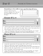
Each
Connection Bar 1 (
pr
EE
-a
) will slide
inside each end of
Connection
Bar
2 (
pr
FF-a
)
. Make sure that the single holes in each Connection Bar 1
face outward and are oriented in the same direction.
•
Using Self Tapping Screws (prG), s
crew the bars together
at a length
matching the
distance between the
Channel Brackets(
pr
BB)
.
•
Insert
the tapered
end
of Connection Bar 3 (
pr
FF-b
)
into
Connection
B
ar
2 (
pr
FF-a
)
and secure
using 3 Self Tapping
Screws
(prG)
.
• Slide
each
Connection Bar 1
(prEE-a)
into the ends
of the
attached bars.
Make sure that the single holes in each Connection Bar 1
face outward
and are oriented in the same direction.
•
Using Self Tapping Screws (prG), screw the bars together at a length
matching the distance between the Channel Brackets(prBB).
2
x
2
x
U
nder
6½
ft
O
ver
6½
ft
1
x
1
x
1
x
A
ssembling
c
onnection
bAr
Depending on the width of your spa this step will vary.
Start by measuring the
distance between the Channel
Brackets(
pr
BB) mounted on
the spa.
Содержание PRO
Страница 1: ...TM PRO Premium Hot Tub Cover Lifter TM ...


