background image

TM

s

teP

 2

m

ounting


brAcket

4

x

4

x

• Place the assembled bracket against the side of the spa. The Side


Mount


Bracket (

pr

AA) must be flush with the side of the spa. 

DO NOT


allow the


Side


Mount Bracket (

pr

AA) to hang over the rounded edge.

(See

 Figures 2 and 3

)

• The rear edge of the Channel Bracket (

pr

BB) should be 2 inches from


the


rear edge of the acrylic 

(See 

Figure 3

)

. The top of the Side Mount


Bracket

(

pr

AA) should be flush with the top of the spa cabinet.

• Use 4 Lag Screws (

pr

A) to mount the Side Mount Bracket (

pr

AA) to


the


side 

of the  spa.
• Cover the Lag Screws (

pr

A) with 

Small 

Screw Caps (

pr

L

)

REPEAT STEPS 1 AND 2 ON THE OPPOSITE SIDE OF THE TUB

Figure 3

Figure 2

Содержание PRO

Страница 1: ...TM PRO Premium Hot Tub Cover Lifter TM ...

Страница 2: ...et prBB Side Mount Bracket prAA Connection Bar 1 prEE a Connection Bar 2 prFF a Connection Bar 3 prFF b Extension Arm prDD 2x Pivot Arm prCC 2x Locking Gas Shock prLS Regular Gas Shock prRS 1x Finger prEE b 2x 1x 2x 1x 1x 2x ...

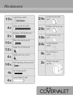
Страница 3: ...S Short Hex Bolt prD Medium Screw Cap prK Small Screw Cap prL Large Washer prM Small Washer prN Long Hex Bolt prB Set Screw prH Lag Screw prA Self Tapping Screw prG Large Lock Nut prE Small Lock Nut prF Screw Sleeve prI 2x 24x 2x 10x 28x 16x 24x 8x 4x 4x 4x 4x 12x 10x 16x ...

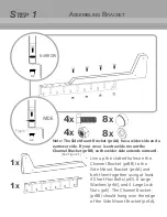
Страница 4: ... using at least 4 Short Hex Bolts prD 8 Large Washers prM and 4 Large Lock Nuts prE The Channel Bracket prBB should hang over the edge of the Side Mount Bracket prAA Note The Side Mount Bracket prAA has a wider side and a narrower side If your cover is extra wide mount the Channel Bracket prBB so the wider side extends outward See Figure 1 Figure 1 NARROW ...

Страница 5: ... edge See Figures 2 and 3 The rear edge of the Channel Bracket prBB should be 2 inches from the rear edge of the acrylic See Figure 3 The top of the Side Mount Bracket prAA should be flush with the top of the spa cabinet Use 4 Lag Screws prA to mount the Side Mount Bracket prAA to the side of the spa Cover the Lag Screws prA with Small Screw Caps prL REPEAT STEPS 1 AND 2 ON THE OPPOSITE SIDE OF TH...

Страница 6: ...sing the Long Hex Bolt prB the Screw Sleeve prI the Small Lock Nut prF and 2 Small Washers prN as shown in Figure 4 Place Medium Screw Caps prK over the Small Lock Nut prF and Long Hex Bolt prB The Locking Gas Shock prLS MUST be installed on the side of the spa where you will operate the lift REPEAT STEP 3 FOR THE OPPOSING SIDE USING THE REGULAR GAS SHOCK prRS Figure 4 2x 2x ...

Страница 7: ...ing the Long Hex Bolt prB Screw Sleeve prI the Small Lock Nut prF and 2 Small Washers pN See Figure 5 Ensure that Pivot Arm prCC swings up and down easily Place Medium Screw Caps prK over the Small Lock Nut prF and the head of the Long Hex Bolt prB REPEAT STEP 4 ON THE OPPOSING SIDE Figure 5 2x 2x ...

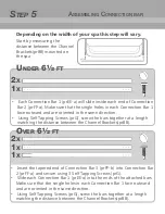
Страница 8: ...nto Connection Bar 2 prFF a and secure using 3 Self Tapping Screws prG Slide each Connection Bar 1 prEE a into the ends of the attached bars Make sure that the single holes in each Connection Bar 1 face outward and are oriented in the same direction Using Self Tapping Screws prG screw the bars together at a length matching the distance between the Channel Brackets prBB 2x 2x Under 6 ft Over 6 ft 1...

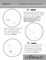
Страница 9: ...larger holes of the Extension Arm prDD Plastic Support prPS and fasten them using Set Screws prH as shown in Figure 9 Figure 8 Figure 9 2x 2x Insert Finger prEE b into the hole on the Extension Arm prDD so it extends inward toward the tub Fasten with Set Screw prH as shown in Figure 7 Figure 7 REPEAT THIS STEP ON THE OTHER EXTENSION ARM BE SURE TO MOUNT THE FINGER FACING THE OPPOSITE DIRECTION Ass...

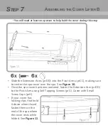
Страница 10: ...r has been centered fasten the Extension Arm prDD to the Pivot Arm using Self Tapping Screws prG Cover with Small Screw Caps prH If your cover has locking clips that hold it down when closed fasten them on the end of the spa where the cover rests while folded See Figure 11 6x 6x You will need at least one person to help hold the cover during this step Figure 11 Figure 10 ...

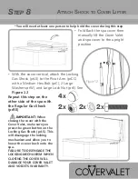
Страница 11: ...um Hex Bolt prC 2 Large Washers prW and Large Lock Nut prE See Figure 12 Repeat this step on the other side of the spa with the Regular Gas Shock prRS IMPORTANT When closing the cover with the Cover Valet make sure you press the green button on the Locking Gas Shock prLS This will disengage the locking mechanism and allow you to lower the cover back onto the spa FAILURE TO DISENGAGE THE LOCKING ME...

Страница 12: ...u specific legal rights and you may have other rights which can vary in different states and countries C Any dispute between the Buyer and California Home Spas INC pertaining to this warranty may at the option of the Buyer be resolved in the State of California USA in according to the rules of the American Arbitration Association D Should any one or more of the terms provisions covenants or condit...

Отзывы: