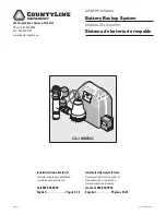


Installation
6
Installation
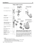
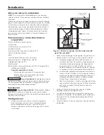
1. Study Figure 2 for suggested layouts. The Easy-Install
layout works better for deeper sumps and allows a
smaller diameter sump (diameter 13-1/2” or larger,
depth more than 22”).
The Alternate layout works better for wider, shallower
sump pits (diameter 18” or larger, depth 18-22”).
The Alternate layout will require that you purchase
(2) 1-1/4” x 90° elbows and (2) 1-1/4” x close pipe
nipples.Other layouts may require more pipe fittings.
2. Find the high water level mark you made on the
discharge pipe in Setup. Cut the pipe at this point
and set the cut-off piece aside for use later. Clean up
and debur the cut ends.
3. Wrap the threads of the Battery Back Up (BBU)
pump and the 1-1/4” x close nipple with
1-1/2 – 2 turns of PTFE pipe thread sealant tape (see
Figure 2). Leave the first thread free of tape and wrap
clockwise (
).
4. Thread the tee, the close nipple, the 1-1/4” x
1-1/4” check valve, and the BBU pump together.
To get them tight, hold the pump and insert a large
screwdriver down through the tee and tighten
the whole assembly with the screwdriver. Do not
overtighten! When the assembly is tight, the pump
and tee should align vertically (no twist – see
Figure 2).
5. Glue the cut-off piece of pipe (which you set aside in
Step 2) into the top of the tee.
NOTICE If your discharge pipe is 1-1/4” inch, glue
one of the reducer bushings supplied with the system
into the tee, then glue the pipe into the bushing.
6. Look at your primary pump to determine if you have
a check valve in or near the pump discharge. If not,
install the auxiliary check valve in the bottom arm
of the tee and install the slip coupling on the check
valve (see Figure 2). For 1-1/4” discharge pipe, glue
the remaining reducer bushing into the slip coupling.
NOTICE If the primary pump assembly already
includes a functioning check valve, do not use the
auxiliary check valve included in the BBU system.
You need one check valve between the primary
pump and the tee (to prevent backflow from either
pump into the sump pit), but two check valves will
restrict the pipe too much.
7. Trial Fit (no glue yet): Place the primary pump
assembly back in the sump pit and add (dry) the tee/
check valve/BBU pump assembly to it. If necessary,
also include the 1-1/2 x 1-1/4 reducer bushing and
the slip coupling and auxiliary check valve (see
NOTICE, above).
8. Measure the assembly against the hanging upper
discharge pipe (where you cut it previously). Mark
the discharge pipe coming up from the tee 1/4”
below the point of overlap (that is, you should have
an air gap of 1/4” after you cut the pipe). Don’t cut
anything yet.
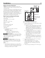
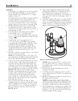
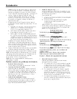
9. Study the assembly in the pit for a moment and then
adjust it so that nothing interferes with the primary
pump or its switch. Mark the joints with a permanent
marker so that you can realign everything after you
pull it out of the pit for gluing (see Figure 3).
NOTICE Take your time with this - it takes care but
isn’t very difficult. Be sure you leave enough room
for the BBU pump’s vertical switch. Mark everything
that might move!
10. After you have marked everything, remove the
assembly from the pit.
11. Cut off the vertical discharge pipe at the cut point
you marked in Step 8. Be sure you are cutting on the
correct mark!
12. Recheck the alignment and glue up all the joints on
the primary pump assembly.
NOTICE You may need to support the assembly,
which won’t balance very well, in order to preserve
the alignment while gluing it. Check this before you
start gluing. Another pair of hands may help here!
13. After the glue has set, slide the hose coupling and its
clamps down over the assembled discharge pipe. If
the pipe is 1-1/4”, be sure to use the two reducing
inserts included with the coupling.
5762 0108
Figure 3 - Mark joints for gluing
Содержание CL1800DC
Страница 24: ......


