CountyLine CL1800DC Скачать руководство пользователя страница 2

Safety • Specifications 

2

Important Safety Instructions

SAVE THESE INSTRUCTIONS - This manual contains 
important instructions that should be followed during 
installation, operation, and maintenance of the product. 

 This is the safety alert symbol. When you see this 

symbol on your pump or in this manual, look for one of 
the following signal words and be alert to the potential 
for personal injury!

 indicates a hazard which, if not avoided, will 

result in death or serious injury.

 indicates a hazard which, if not avoided, 

could result in death or serious injury.

 indicates a hazard which, if not avoided, 

could result in minor or moderate injury.
NOTICE addresses practices not related to 
personal injury.
Carefully read and follow all safety instructions in this 
manual and on pump.
Keep safety labels in good condition. Replace missing or 
damaged safety labels.
California Proposition 65 Warning

 This product and related accessories contain 

chemicals known to the State of California to cause 
cancer, birth defects or other reproductive harm.
1.  To avoid risk of serious bodily injury due to electrical 

shock or burns and property damage due to flooding, read 
the safety instructions carefully before installing pump.


 Risk of burns. Battery posts, terminals 

and related accessories contain lead and lead 
compounds, chemicals known to the State of 
California to cause cancer and reproductive harm. 
Wash hands after handling.


 Risk of explosion and hazardous gas. 

Connect and disconnect DC output terminals only 
after removing the charger from the AC outlet. Never 
allow the DC terminals to touch each other.


 Risk of electric shock. Can shock, burn 

or kill. Do not plug in or unplug battery charger 
while standing on a wet floor or in water. Be sure 
one hand is free when plugging in or unplugging 
charger. If basement floor is wet, disconnect power 
to basement before walking on floor.


 Risk of flooding. Can cause personal 

injury and/or property damage. Do not run pump 
dry. To do so will damage equipment.

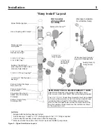
2.  Use this system only for backup sump pump duty 

in a residential application. It is not designed as a 
primary sump pump.

3.  Follow local and/or national plumbing and electrical 

codes when installing the system. A ground fault 
circuit interrupter (GFCI) is recommended for use on 
any electrical appliance submerged in water.

4.  Do not lift pump by electrical cord.
 

 Risk of electric shock. Can shock, burn 

or kill. Do not lift the pump by the electrical cord; lift 
pump only by the discharge pipe, lifting ring or handle 
on the pump. Lifting by the cord can damage the cord.

5.  Pump clear water only with this pump.
6.  Pump is permanently lubricated at the factory. Do 

not try to lubricate it!

7.  Keep battery charger and battery box off of the floor 

and in a dry, cool, well ventilated area.


 Risk of hazardous gas. If a Carbon 

Monoxide (CO) sensor is installed, it must be at 
least 15 feet away from battery charger in order 
to avoid nuisance CO alarms. Please refer to 
your CO detector’s installation instructions for 
more information.

8.  To avoid danger of fire or explosion, keep sparks and 

flame (pilot light) away from battery.

9.  Maximum vertical pumping distance is 16 feet (4.9m).
10. Make sure sump is clear of debris. Debris can 

damage the pump which can result in flooding.

General Information

The battery back-up sump system is not a sub stitute for your 

primary sump pump. It is designed to temporarily back up 

your primary sump pump during a power outage or other 

problem which prevents normal operation of the primary 

pump. Do not use this system to pump flammable liquids or 

chemicals. Pump clear water only with this pump.
Keep the battery charger dry and protected from damage.
This system is designed to work with a deep cycle marine 

battery, either a flooded lead-acid battery or a sealed 

maintenance free lead-acid AGM battery. In an emergency 

(such as an extended power outage) which depletes the 

system deep cycle battery, your automobile battery may be 

temporarily substituted. Be sure to replace the system deep 

cycle battery as soon as possible. Use of an automobile 

battery instead of a deep cycle battery in this system 

will significantly reduce the system’s total performance. 

Automobile batteries are not designed for this type of 

application and will be quickly ruined by the repeated 

charge/discharge cycling.

Specifications - 

Capacity Ratings with a 100 Ampere-Hour Deep Cycle Marine Battery

Vertical Pumping Distance

8’ (2.4 m)

10’ (3.0 m)

12’ (3.7 m)

16’ (4.9 m)

Gallons Per Hour

1,440

1,200

840

No Flow at this Height

Aproximate Hrs Available

10

11.5

13

Total Gallons Pumped

8,500

7,000

5,000

*  These flow rates were obtained with a constant 12.7 VDC battery source. The actual GPH will vary due to a reduction in output voltage from the battery as it discharges.
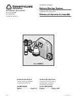
Содержание CL1800DC

Страница 1: ...WI 53115 Phone 800 535 4950 Fax 800 526 3757 www tractorsupply com Installation Operation Parts For further operating installation or maintenance assistance Call 800 535 4950 English Pages 2 12 Instal...

Страница 2: ...trical appliance submerged in water 4 Do not lift pump by electrical cord Risk of electric shock Can shock burn or kill Do not lift the pump by the electrical cord lift pump only by the discharge pipe...

Страница 3: ...products used in commercial rental applications Sewage Pumps DO NOT return a sewage pump that has been installed to your retail store Contact CountyLine Customer Service Sewage pumps that have seen se...

Страница 4: ...or fuse box turn off the electrical power to the sump pump before beginning this installation Setup 1 Locate the high water level in your sump pit that is the water level at which the existing primar...

Страница 5: ...Battery Backup System Use if necessary to adapt a 1 1 4 discharge pipe to the 1 1 2 fittings supplied Use to adapt the auxiliary check valve to the discharge pipe Water level when the switch shuts off...

Страница 6: ...pump assembly already includes a functioning check valve do not use the auxiliary check valve included in the BBU system You need one check valve between the primary pump and the tee to prevent backfl...

Страница 7: ...ure 4 and connect the second battery in the same manner Connect the positive battery lead red to the positive Charger Controller terminal red Connect the negative battery lead black to the negative te...

Страница 8: ...lack on the charger and the positive on the battery must connect to the positive on the charger Reversing the battery connections will cause the System Alert and Silenced Audible Alarm LEDs to flash 3...

Страница 9: ...size so it will fit in the battery box maximum size 13 long 7 wide and 10 high 330 2mm x 177 8mm x 254mm including terminals and supply enough voltage for full performance Battery Maintenance Risk of...

Страница 10: ...ashing LED Battery pre qualification test is running TABLE II Operating Code Displays LEDs Lighted Continuously or Flashing Control LED Continuous Illumination Indicates Normal Operation AC Power AC p...

Страница 11: ...the same time to reset the charger Thermal Runaway condition LED is Flashing Slow LED is OFF LED is ON Continuously 5766 0108 Battery Charge is Below 20 Stop pump allow battery to charge AC must be on...

Страница 12: ...ple 1 1 4 NPT x Close 1G Check Valve Assembly 1 1 4 FNPT x 1 1 4 FNPT 2 DC Backup Pump PS17 118 3 Vertical Float Switch Package PS198 269REP 4 Charger PS217 1512 5 Battery Case Complete PS17 1512 6 AC...

Страница 13: ...recomienda usar un disyuntor a tierra GFCI con cualquier aparato el ctrico sumergido en agua 4 No levante la bomba por el cord n el ctrico Riesgo de choque el ctrico Puede provocar choque quemadura o...

Страница 14: ...ilizados en aplicaciones comerciales o de alquiler Bombas cloacales NO devuelva una bomba cloacal que se haya instalado a su tienda minorista Comun quese con el Departamento de Atenci n al Cliente de...

Страница 15: ...instalaci n Configuraci n 1 Ubique el nivel de agua alto en su foso de recogida es decir el nivel del agua en la cual se enciende la bomba de sumidero presente primaria consulte la Figura 1 Marque est...

Страница 16: ...e descarga superior Empalme de manguera con abrazaderas Trozo cortado de la tuber a de descarga Manguito reductor corredizo de 1 1 2 x 1 1 4 Te de 1 1 2 x 1 1 2 corredizo x 1 1 4 FNPT Empalme corrediz...

Страница 17: ...de la bomba primaria ya incluye una v lvula de retenci n que funciona no use la v lvula de retenci n auxiliar incluida en el sistema BBU Usted necesitar una v lvula de retenci n entre la bomba primari...

Страница 18: ...as use el segundo juego de bornes consulte Figuras 4 y conecte la segunda bater a de la misma manera Conecte el conductor positivo de la bater a rojo al borne positivo del Cargador Control rojo Conect...

Страница 19: ...tivo negro en el cargador y el positivo en la bater a se debe conectar al positivo en el cargador Si se invierten las conexiones de la bater a los diodos emisores de luz de Alerta del sistema y Alarma...

Страница 20: ...mm x 177 8 mm x 254 mm incluyendo los bornes y suministre suficiente tensi n para un rendimiento completo Mantenimiento de la bater a Riesgos de quemaduras Las patillas de las bater as los terminales...

Страница 21: ...lterna CA se ilumina siempre que el sistema est enchufado en un circuito de corriente alterna CA activo Cuadro II Visualizaciones de los c digos de operaci n Diodos emisores de luz DEL continuamente i...

Страница 22: ...uevo acumulador cido de plomo de 12V Cambiar la bater a por un nuevo acumulador cido de plomo de 12V Medida La bomba se apagar la bater a no est cargando Cambiar la bater a DEL est centelleando r pido...

Страница 23: ...lvula de retenci n 1 1 4 FNPT x 1 1 4 FNPT 2 Bomba de respaldo de CC PS17 118 3 Paquete de interruptor de flotador vertical PS198 269REP 4 Cargador PS217 1512 5 Caja de la bater a completa PS17 1512...

Страница 24: ......

Отзывы: