
5.4.1
SYSTEM PARAMETER SETTING
If machine had replace a new computer board, it needs input machine parameter value into new computer
board. Then do the self calculation to save the setting.
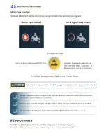
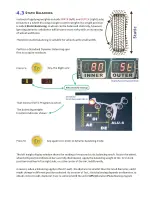
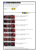
5.4.2 press Fn +C to-
gether
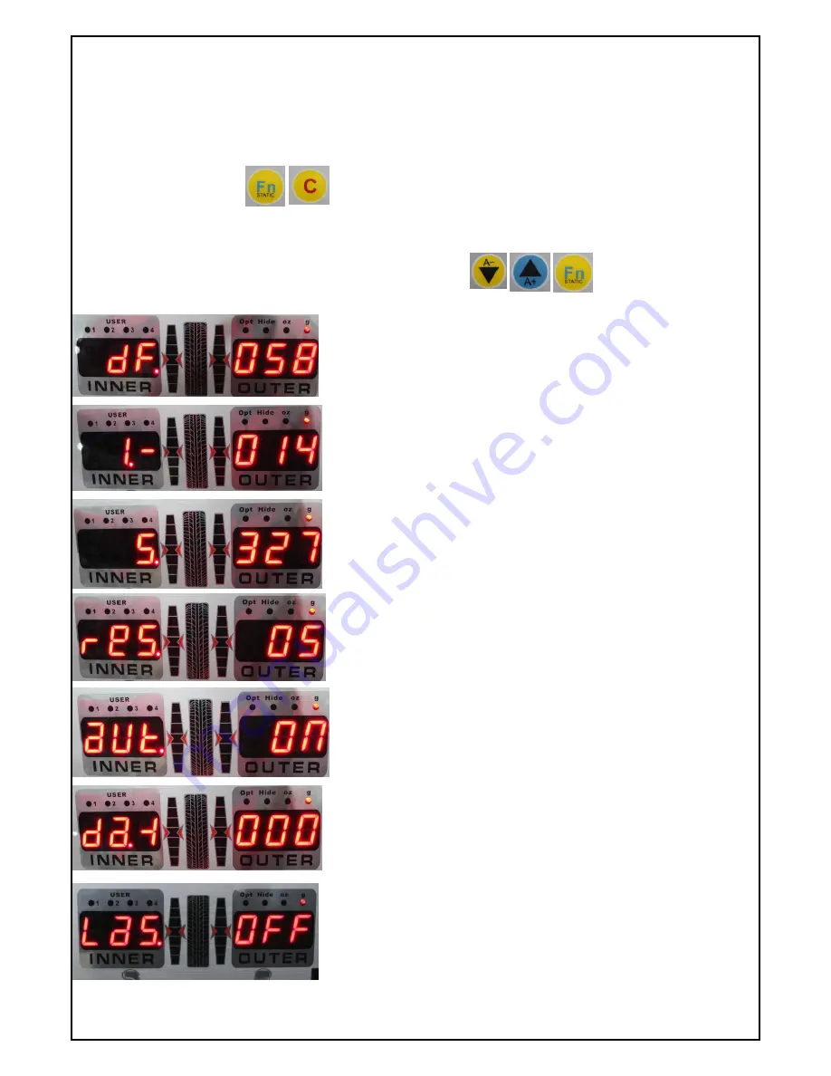
Press B+ or B – to adjust the DF value of offset error.
Press A+ to enter next parameter setting.
Do not change the parameter value, unless the result of balancing is off.
Please contact your reseller or manufacturing for after service before make any change.
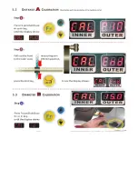
5.4.1 turn on the machine and wait this homepage.
Display will shows below
picture
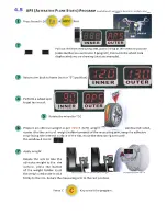
5.4.3 press A
-, A+, Fn key in sequence to enter system parameter setting
Press B+ or B – to adjust the I value of axial error.
Press A+ to enter next parameter setting.
Press B+ or B – to adjust the S value of angle error.
Press A+ to enter next parameter setting.
Press B+ or B – to adjust the RES value of Residual value of showing
Press A+ to enter next parameter setting.
Press B+ or B – to adjust equip the width measuring arm.
Press A+ to enter next parameter setting.
Press B+ or B – to adjust diameter measurement. (1 unit = 0.1 inch).
Press A+ to enter next parameter setting.
Press B+ or B – to adjust laser pointer on or off.
Press A+ to return homepage.
Содержание SP711N
Страница 2: ......
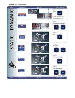
Страница 3: ...2 Key combinationoverview ...
Страница 4: ......
Страница 5: ......
Страница 6: ......
Страница 7: ......
Страница 8: ......
Страница 9: ......
Страница 10: ......
Страница 11: ......
Страница 12: ......
Страница 13: ......
Страница 14: ......
Страница 15: ......
Страница 16: ......
Страница 17: ......
Страница 18: ......
Страница 19: ......
Страница 20: ......
Страница 21: ......
Страница 22: ......
Страница 23: ......
Страница 25: ......


