
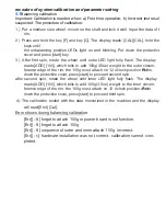

rocedure of system calibration and parameter setting
5.1
Balancing calibration
Important: Calibration is needed when: a) First time operation; b) Incorrect test result
suspected. The procedure of calibration:
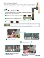
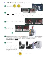
1) Put a medium size wheel, mount on the shaft and lock it well. Input the data of the
rim.
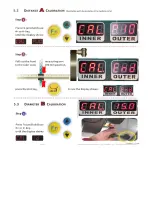
2) Press and hold the key [F] and key [C]. The display reads: [CAL][CAL], hold the
keys until
the unbalancing position LEDs light on and blinking. Put down the protective
cover and press [start] key.
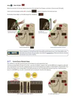
3) After first spin, rotate the wheel until outer LED light fully flash. The display
reads:[ADD] [100], which tells to add 100g(3.5oz) weight to the outer circum-
ference edge of the rim. the 100g must attach on 12 o'clock position of rim.
Put
down the protective cover, press [start] to proceed second spin.
after second spin, rotate the wheel until inner LED light fully flash. The display
reads:[ADD] [100], which tells to add 100g(3.5oz) weight to the inner circum-
ference edge of the rim. the 100g must attach on 12 o'clock position of rim.
Put
down the protective cover, press [start] to proceed third spin.
4)The calibration ended with the data memorized in the machine and the display
will read:[End] [Cal].
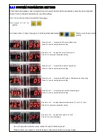
Error shows during balancing calibration.
[Err][ -8-] forget to attach 100g or power board is out function.
[Err][ -9-] forget to attach 100g
[Err][ -6-] sequence of outer and inner attach 100g incorrect.
[Err][ -r-] hardware installation was not correct. calibration cannot com-
pleted.
Содержание SP711N
Страница 2: ......
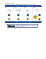
Страница 3: ...2 Key combinationoverview ...
Страница 4: ......
Страница 5: ......
Страница 6: ......
Страница 7: ......
Страница 8: ......
Страница 9: ......
Страница 10: ......
Страница 11: ......
Страница 12: ......
Страница 13: ......
Страница 14: ......
Страница 15: ......
Страница 16: ......
Страница 17: ......
Страница 18: ......
Страница 19: ......
Страница 20: ......
Страница 21: ......
Страница 22: ......
Страница 23: ......
Страница 25: ......


