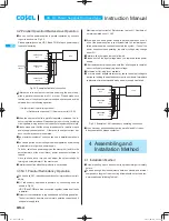
3.2 Parallel Operation/Master-slave Operation
¡
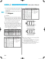
You can use the power supplies in parallel operation by connect-
ing units as shown in Fig.3.2.
Please parallelly connect VB, CB and COM of each power supply
in parallel operation.
+V
VB
CB
COM
-V
FETA2500B
No.1
maximum
10units
Load
+V
VB
CB
COM
-V
FETA2500B
No.2
+V
VB
CB
COM
-V
FETA2500B
No.10
Fig.3.2 Example of parallel connection
¡
Differences in the output current values among the power sup-
plies in parallel connection are 5% at most. Please make sure
that the sum of the output current values does not exceed a value
obtained from the following equation.
(Output current in parallel operation)
= (Rated current per unit)
X
(Number of units)
X
0.95
¡
When the number of units in parallel operation increases, the in-
put current also increases. Please design input circuitry (including
circuit pattern, wiring and current capacity for equipment) carefully.
¡
Please make sure that the wiring impedance of a load from each
power supply becomes even. Otherwise, the output current bal-
ance circuit may become inoperative.
¡
The maximum number of units you can use in parallel operation is
10.
¡
You can adjust the output voltage in parallel operation by adjusting
a potentiometer of just one power supply.
To do so, select one power supply as the master unit and turn the
potentiometers of the other (slave) power supplies clockwise to
the end.
Once you have done this, you can adjust the output voltage by
turning the potentiometer of the master unit.
¡
Parallel connection with other products is not allowed.
3.3 N+1 Parallel Redundancy Operation
¡
You can have N+1 redundancy operation for improved system reli-
ability.
¡
N+1 redundancy operation is possible by connecting units as
shown in Fig.3.3.
VB, CB and COM are also connected together between all units
in parallel.
¡
Output current calculation is required based on following equation.
The current has to be more over normal operation current even if
one power supply fails.
Maximum output current
[
Rated current per unit
X
Numbers of
normal operated units
X
0.95
¡
If you add one extra power supply in parallel operation, even if
one of the power supplies in your system fails, the remaining non-
failed power supplies continue to sustain the system. If one of the
power supplies stops operating, the output voltage may change
about 5%.
¡
Parallel with other products is not allowed.
¡
Please shut off the input voltage when you replace a failed power
supply.
¡
After replacement, please make sure that all wirings are complet-
ed correctly, before re-applying input voltage.
¡
Hot-swap or Hot-plug is not available.
¡
2 or more power supplies failures may cause the output voltage to
decrease, lending the application system to shut down. Immediate
replacement is recommended when a power supply has failed.
+V
VB
CB
COM
-V
FETA2500B
No.1
Load
+V
VB
CB
COM
-V
FETA2500B
No.2
+V
VB
CB
COM
-V
FETA2500B
No.10
Fig.3.3 Example of N+1 redundancy operating connection
¡
If you have any questions about series, parallel and N+1 redun-
dancy operations, please contact us.
4 Assembling and
Installation Method
4.1 Installation Method
¡
Screw mounting has to be consider the product weight for safety
fi xture.
¡
To keep enough insulation distance between screws and internal
components, length of the mounting screw should not exceed rec-
ommendation as following Table4.1.
AC-DC Power Supplies Enclosed type
Instruction Manual
FETA-10
FETA
me̲feta1.indd 10
me feta1 indd 10
2013/09/09 14:28:40
2013/09/09 14:28:40


