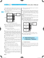
1 Terminal Blocks
1
2
3
4
5
6
7
8
9
0
1
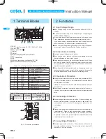
AC (L) Input Terminals AC170 - 264V 1
f
47 - 63Hz
2
AC (N) (M4)
3
Frame ground (M4
)
4
+Output
5
-Output
6
Output voltage adjustable potentiometer
7
CN1
8
CN2
Connectors
9
LED for output voltage confi rmation (DC_OK)
0
LED for fault condition detection (ALARM)
Table 1.1 Pin Confi guration and Functions of CN1, CN2
Pin No.
Pin Name
Function
1
AUXG
Auxiliary power output (GND)
2
AUX
Auxiliary power output
3
WRNG
Warning signal (GND)
4
WRN
Warning signal
5
PGG
Alarm signal (GND)
6
PG
Alarm signal
7
RCG
Remote ON/OFF (GND)
8
RC
Remote ON/OFF
9
COM
Signal ground
10
TRM
Adjustment of output voltage
11
VB
Voltage Balance
12
CB
Current Balance
Table 1.2 Matching connectors and terminals on CN1, CN2
Connector
Housing
Terminal
Mfr.
CN1
S12B-PUDSS-1 PUDP-12V-S
Reel : SPUD-001T-P0.5
or
SPUD-002T-P0.5
J.S.T
CN2
1
2
11
12
1
2
11
12
CN1
CN2
Fig.1.1 Connector pin numbers
2 Functions
2.1 Input Voltage Range
¡
Input voltage range of the power supplies is from AC170V to
AC264V.
¡
In cases that conform with safety standard, input voltage range is
AC200-AC240V (50/60Hz).
¡
If input value doesn’t fall within above range, a unit may not oper-
ate in accordance with specifi cations and/or start hunting or fail.
If you need to apply a square waveform input voltage, which is
commonly used in UPS and inverters, please contact us.
¡
When the input voltage changes suddenly, the output voltage ac-
curacy might exceed the specifi cation. Please contact us.
2.2 Inrush Current Limiting
¡
An inrush current limiting circuit is built-in.
¡
If you need to use a switch on the input side, please select one
that can withstand an input inrush current.
¡
Relay technique is used in the inrush current limiting circuit. When
you turn the power ON/OFF repeatedly within a short period of
time, please have enough intervals so that the inrush current limit-
ing circuit becomes operative.
¡
When the switch of the input is turned on, the primary inrush cur-
rent and secondary inrush current will be generated because the
relay technique is used for the inrush current limiting circuit.
2.3 Overcurrent Protection
¡
An overcurrent protection circuit is built-in and activated at 105%
- 120% of the rated current. A unit automatically recovers when a
fault condition is removed.
Please do not use a unit in short circuit and/or under an overcur-
rent condition.
¡
Low-voltage protection is activated when output voltage is re-
duced by over current protection under the low-voltage protection
value.
2.4 Overvoltage Protection
¡
An overvoltage protection circuit is built-in. If the overvoltage pro-
tection circuit is activated, shut down the input voltage, wait 10 or
more seconds and turn on the AC input again to recover the out-
put voltage.
Note :
¡
Please avoid applying a voltage exceeding the rated voltage to an
output terminal. Doing so may cause a power supply to malfunc-
tion or fail. If you cannot avoid doing so, for example, if you need
to operate a motor, etc., please install an external diode on the
output terminal to protect the unit.
2.5 Low-voltage Protection
¡
Low-voltage protection is built-in. This protection will shut down
the output with the activation. To restart the output, recycle AC
input after 10 or more seconds.
AC-DC Power Supplies Enclosed type
Instruction Manual
FETA-6
FETA
me̲feta1.indd 6
me feta1 indd 6
2013/09/09 14:28:39
2013/09/09 14:28:39


