MOBILTEX® DATA LTD.
Calgary, Alberta
www.corTalk.com
TITLE:
uDL2 Configuration and Operation Guide
DOCUMENT NO.:
UDL2-MAN-001
SHEET:
24 of 28
REV:
1.07
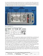
The bottom of the uDL2 includes a magnet which allows the device to be attached to ferrous surfaces. There are also
two holes in the base of the device that allow the device to be secured to a string or structural wire in applications where
it is dropped down a tube such as test point stations. The GPS antenna is located on the end opposite the uDL2 connector.
Even though the GPS antenna in the uDL2 is reasonably omni-directional, best GPS signal reception will generally
occur when the GPS antenna system is pointed upwards towards the sky.
Figure 30 uDL2 Back View
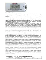
The uDL2 has a custom LCD display that is illustrated below:
Figure 31 uDL2 LCD Display
The primary purpose of the LCD is to provide the installer/user with an indication that they are connected to and
measuring the desired signal(s). The uDL2 has a high resolution measurement system that records the measurements in
high resolution to the measurement storage memory. The LCD provides 3 ½ digits of measurement information.
When the analog cable is first attached, the uDL2 will enter a real-time measurement display mode for a period of 1
minute. During this time the uDL2 doesn’t store information to memory and it provides real-time measurement data on
the LCD which is updated every 2 seconds. The “SAMPLE” icon continuously illuminates during this real-time display
mode. After the real-time mode expires, the “SAMPLE” icon will turn off and then flash during each measurement.
When a DC Voltage is being measured the LCD “DC” icon will illuminate. The LCD will not show any polarity mark
for positive signals. The “-“ icon will illuminate for negative voltages. When an AC voltage is being measured, the
“AC” icon will be illuminated. When temperature is being measured the degree symbol will illuminate.
The battery symbol on the right of the LCD provides an approximate indication of remaining battery capacity. The
battery is at nearly full capacity when all three internal battery bars are illuminated. As the battery charge becomes
depleted, the number of bars displayed is reduced. When the battery is nearly depleted there will not be any remaining
bars and the LCD will display “Lo”. Sampling operation will cease at that point. The “Lo” indication will remain even
after the analog cable is disconnected.

