


MOBILTEX® DATA LTD.
Calgary, Alberta
www.corTalk.com
TITLE:
uDL2 Configuration and Operation Guide
DOCUMENT NO.:
UDL2-MAN-001
SHEET:
23 of 28
REV:
1.07
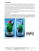
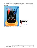
Dual Potential Mode
The black wire is connected to the common reference point, which in many cases is a reference cell. The red wire is
connected to the first potential measurement point, which may be a pipe or a structure. The blue wire is connected to
the second potential measurement point, which again may be a pipe or a structure. Figure 29 shows a typical attachment
at a test station.
V1
V2
Ref
Black
Potential 2
Blue
Potential 1
Red
uDL2 (Dual Potential Mode)
Figure 29 Dual Potential Analog Cable Attachment to a Test Station


