Page 6
SRP 003-304 • Issue 9 • July 2004
9.5
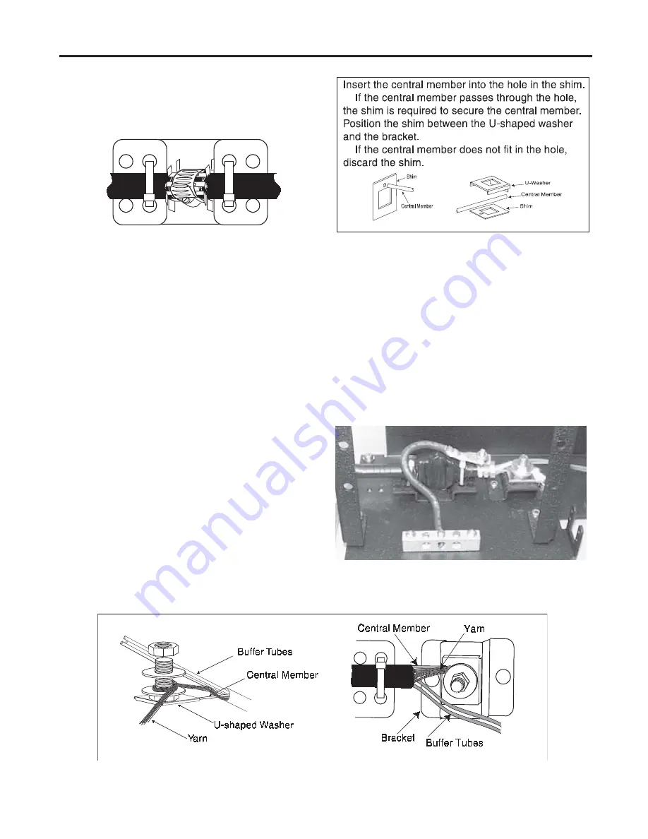
Secure the cable to the sheath retention
bracket using cable ties. Make sure the tabs on
the clamp material are in the recessed section
of the bracket (Figure 8).
9.6
When central member strain-relief is
required, the central member bolt must be
installed into the strain-relief bracket as shown
(Figure 9).
NOTE:
Smaller diameter central members require
a shim to make sure they are adequately secured in
the central member clamp. Use a central member
clamp shim when necessary (Figure 10).
a) Remove the top nut and the two washers
from the bracket.
b) Loosen the remaining nut.
c) Insert the central member of the cable
between the bracket and the U-shaped
washer.
d) Arrange the buffer tubes to ensure
clearance around the central member
clamp assembly and hardware.
e) Tighten the hex nut.
f) Install the two flat washers.
g) Loosely install the other hex nut.
h) Wrap the strength member yarn in a
clockwise direction around the bolt and
between the flat washers.
i)
Tighten the second hex nut.
j)
Trim off the excess yarn and central
member.
NOTE:
The exposed length of the central member
(after strain-relief) is to be less than or equal to 6.5
cm (2
1
/
2
inch) between the U-shaped washer and
the end of the cable sheath.
9.7
When cable grounding is necessary, use
the hardware ground kit (purchased separately).
Install the ground kit as shown in Figure 11.
Figure 8
Figure 9
Figure 10
Figure 11
•
•


