Page 10
SRP 003-304 • Issue 9 • July 2004
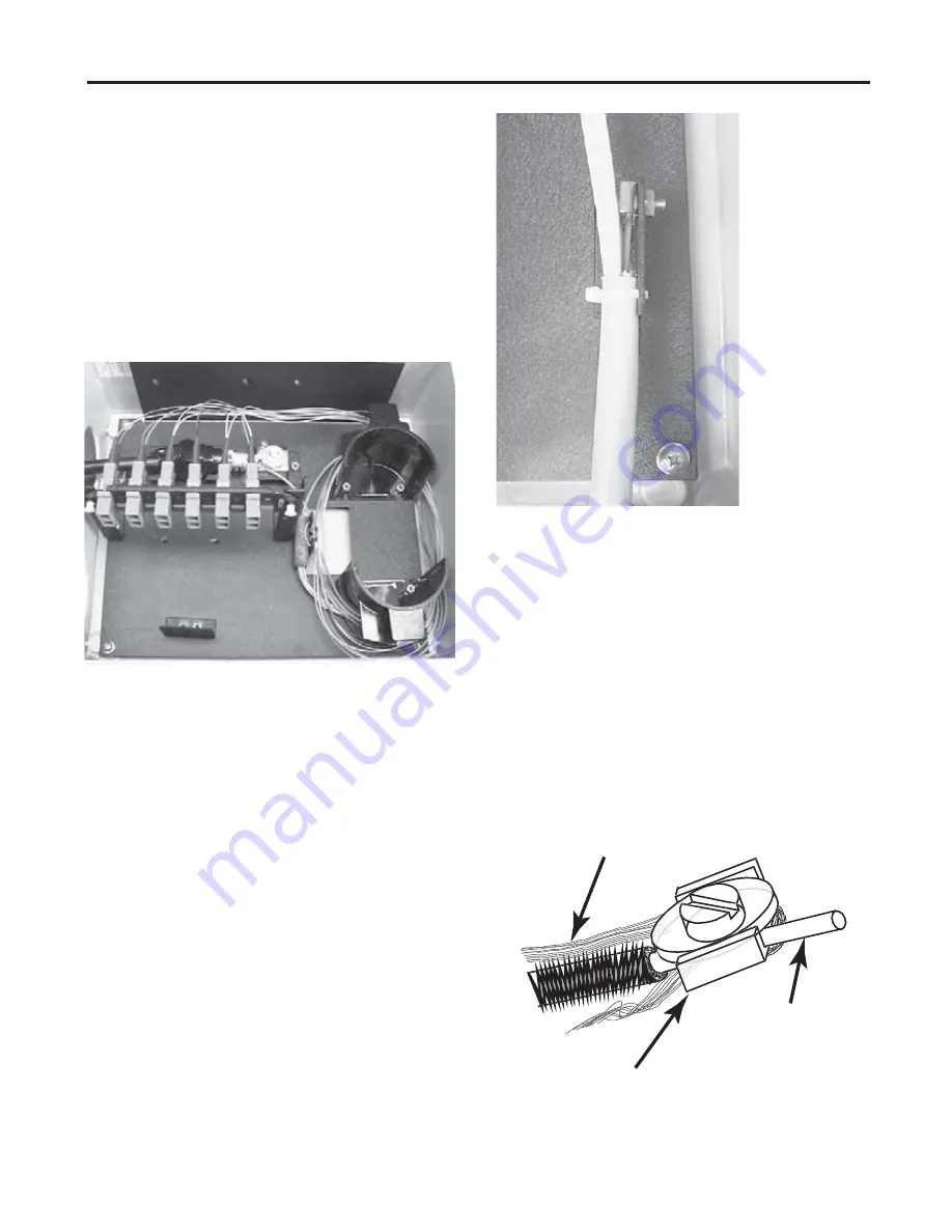
Figure 22
12.5
Route the fiber in the fan-out tubing
around the guides and plug connectors into the
connector panel (Figure 21). Refer to the
previous connector care instructions to avoid
damaging the connectors during installation.
12.6
Label the connector end of the pigtail
with its port identifier. Record information
appropriately on the record label inside the
front door.
NOTE:
Accurate record keeping is imperative
for an organized installation.
13. Installing Drop Cables
13.1
The EDC is designed to accept up to six
drop cables. Feed the drop cable through the
fitting you installed on the right at the base of
the closure.
NOTE:
Drop cable subunit lengths should be
approximately 130 cm (51 inches) in length in order
to provide two loops of fiber slack around the radius
guides.
13.2
If the drop cables do not include central
members, secure the cables to the bracket using
a loosely tightened cable tie. When central
member strain-relief is necessary, remove the
drop cable strain-relief bracket and secure the
cable to the bracket using a cable tie as shown
(Figure 22).
a) Install the 8-32x5/8 screw from the front
side of the strain-relief bracket through the
flat washer and U-shaped washer. Loosely
install the hex nut.
b) Insert the central member of the cable
between the flat washer and the U-shaped
washer (Figure 23).
c) From the front side of the strain-relief
bracket, wrap the strength member yarn in a
clockwise direction around the screw and
under the U-shaped washer (Figure 23).
d) Tighten the hex nut.
e) If the central member is metallic, place the
eye of a ground wire (#6 AWG, purchased
separately in appropriate length from any
electrical supply store) under the U-shaped
washer or under the flat washer.
Figure 21
Figure 23
Strength-Member Yarn
U-Shaped Washer
Central Member


