


20
First use handle (15, Fig. D) to tip the arm to this position.
Agire quindi, prima di tutto, sulla maniglia (15, Fig. D) per ribalta-
re il braccio in questa posizione.
azionare il manipolatore verso sinistra (c): il carrello portautensili
e la pedana mobile (13, Fig. D) devono avvicinarsi all'auto-
centrante (3, Fig. A); azionare il manipolatore verso destra (d):
il carrello e la pedana devono allontanarsi dall'autocentrante.
2)
Azionare l'interruttore (9, Fig. C) verso l'alto: i bracci dell'au-
tocentrante (3, Fig. A) devono aprirsi; azionare l'interruttore verso
il basso: i bracci dell'autocentrante devono chiudersi.
1)
Move the joystick (8, Fig. C) up (a): the spindle carrier arm (2,
Fig. A) should lift; move the joystick down (b): the arm should
lower.
1)
Azionare il manipolatore (8, Fig. C) verso l'alto (a): il braccio
porta autocentrante (2, Fig. A) deve sollevarsi; azionare il ma-
nipolatore verso il basso (b): il braccio porta autocentrante
deve abbassarsi;
DANGER!
When the spindle carrier arm is lowered, there is
always a potential for crushing anything in its
movement range. Always work from the position given
in the instructions keep well
out of the working range
of the various moving
arms.
ATTENZIONE!
L'abbassamento del braccio porta autocentrante crea
dei potenziali punti di schiacciamento. Operare
sempre dalla posizione indicata nelle istruzioni
mantenendosi al di fuori
del raggio di azione
dei vari bracci
operanti.
Move the joystick towards the left (c): the tool carriage and
the mobile platform (13, Fig. D) should move towards the spin-
dle (3, Fig. A); move the joystick towards the right (d) the car-
riage and platform should move away from the spindle.
2)
Turn switch lever (9, Fig. C) towards the top: the spindle arms
(3, Fig. A) should open; move the lever down and the spindle
arms should close.
ATTENZIONE!
Le operazioni di apertura e chiusura dell'autocen-
trante creano potenziali punti di schiacciamento.
Operare esclusivamente dalle posizioni indicate
nelle istruzioni d'uso
mantenedosi al di fuori
del raggio di azione
dell'autocentrante.
3)
Premere il pedale a bilanciere (10, Fig. C) sul lato destro:
l'autocentrante (3, Fig. A) deve ruotare in senso orario; preme-
re il pedale a bilanciere sul lato sinistro: l'autocentrante deve
ruotare in senso antiorario.
3)
Depress the right pedal (10, Fig. C): the spindle (3, Fig. A)
should turn clockwise; depress the left pedal: the spindle should
turn anticlockwise.
DANGER!
When the spindle arms open or closed, there is always
a potential for crushing anything in their movement
range. Always work from the position given in the
instructions keep well out
of the spindle’s working
range.
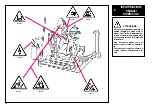
CAUTION!
Do not move your face close to the tool
carrier arm when you release it to tip it
as needed.
ATTENZIONE!
Non tenere il viso vicino al braccio porta
utensili mentre lo si "sgancia" per
effettuare il ribaltamento.
D
C
E/1
17
18
15
13
14


