2DF
1-3-46
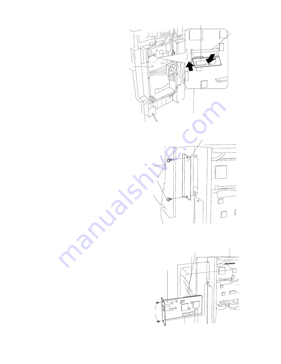
4. Insert the RTC board at an angle into the
RTC board slot on the main PCB.
5. Push the free end of the RTC board down
toward the fax board.
6. Remove 2 screws, and take off the cover.
7. Firmly push connector CN1 on the scanner
board all the way into connector CN50 on the
main PCB.
8. Fasten the scanner board with 2 screws.
Figure 1-3-98
Figure 1-3-96
Figure 1-3-97
RTC board slot
RTC board
Main PCB
Cover
Screws
Connector CN1
Connector CN50
Screws
Scanner board
Содержание Ri 2530
Страница 59: ...2DF 1 3 39 This page is intentionally left blank...
Страница 124: ...1 4 37 2DF This page is intentionally left blank...
Страница 130: ...1 4 41 2DF This page is intentionally left blank...
Страница 138: ...1 4 47 2DF This page is intentionally left blank...
Страница 151: ...1 4 56 2DF This page is intentionally left blank...
Страница 326: ...AD 63...
Страница 329: ...3CX 1 1 2 1 1 2 Part names Figure 1 1 1 Duplex unit...
Страница 330: ...3CX 1 1 3 1 1 3 Machine cross section Figure 1 1 2 Paper path Duplex unit...
Страница 346: ...DF 78...
Страница 349: ...3B5 1 1 2 1 1 2 Part names Figure 1 1 1 1 Intermediate tray 2 JAM release lever 3 Eject tray...
Страница 383: ...J 1402...
Страница 386: ...3B6 1 1 2 1 1 2 Part names Figure 1 1 1 1 Job separator tray 2 LED...
Страница 387: ...3B6 1 1 3 1 1 3 Machine cross section Figure 1 1 2 Paper path...
Страница 388: ...3B6 1 1 4 1 1 4 Drive system Figure 1 1 3 1 Gear 20 2 Gear 28 3 Gear 28 4 Eject roller gear...
Страница 399: ...PF 70...
Страница 401: ...1 1 2 3CC 2 4 Appendixes Timing chart No 1 2 4 1 Timing chart No 2 2 4 2 Wiring diagram 2 4 3...
Страница 403: ...3CC 1 1 2 1 1 2 Parts names 1 Upper drawer 2 Lower drawer 3 Desk left cover Figure 1 1 1 3 1 2...
Страница 404: ...3CC 1 1 3 1 1 3 Machine cross section Paper path Figure 1 1 2 Machine cross section...
Страница 436: ...RA 1...
Страница 438: ...3CP 1 1 1 1 1 1 Part names Figure 1 1 1 Switchback unit Switchback unit open close lever...
Страница 439: ...3CP 1 1 2 1 1 2 Machine cross section Figure 1 1 2 Paper path Switchback unit...
Страница 440: ...3CP 1 1 3 1 1 3 Drive system Figure 1 1 3 1 Switchback motor gear 2 Eject motor gear 3 Gear 23 31 4 Gear 21...
Страница 456: ...PF 75...
Страница 458: ...1 1 2 5FF 2 4 Appendixes Timing chart No 1 2 4 1 Timing chart No 2 2 4 2 Wiring diagram 2 4 3...
Страница 461: ...5FF 1 1 3 1 1 3 Machine cross section Paper path Figure 1 1 3 Machine cross section...
Страница 499: ...Fax System C...
Страница 501: ...1 1 2 3CM...
Страница 509: ...3CM 1 1 8...
Страница 553: ...3CM 1 3 40...
Страница 565: ...3CM 1 5 2...
Страница 570: ...3CM 2 1 2...
Страница 581: ...Fax System F...


