Revision
04
February 19, 1998
363-765-104-04
26
PairGain
Engineering - Plant Series
FRE-765
List
4x
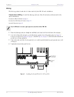
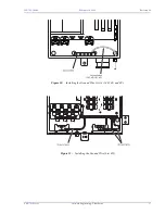
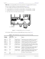
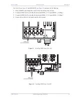
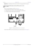
For the FRE-765 List 4F enclosures, connect the subscriber connections to the Amphenol-ended cable stub per
1
Route the subscriber line cable through the bottom of the enclosure.
2
Connect the subscriber line cable to the Amphenol-ended cable coming off the protector field.
3
Secure with a cable tie to the bracket near the cable entrance.
*
For the FRE-765 List 4F RT Enclosure, the cable on the rear of the protection block
subassembly is installed in connector P1 on the RT enclosure backplane.
†
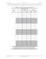
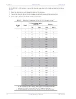
Shaded terminations used only with the 8 Channel POTS or 4 Channel DDS Units.
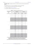
Table 17.
Subscriber Terminations for Lists 4F (12/24 channel systems)
*
†
Channel
Unit
Circuit
25-Pair Amphenol (male)
Line Cable
Protector
Tip
Ring
Strip
Socket
1
26
1
PB1
1
2
27
2
PB1
2
3
28
3
PB1
3
1
4
29
4
PB1
4
5
30
5
PB1
5
6
31
6
PB1
6
7
32
7
PB1
7
8
33
8
PB1
8
1
34
9
PB1
9
2
35
10
PB1
10
3
36
11
PB2
1
2
4
37
12
PB2
2
5
38
13
PB2
3
6
39
14
PB2
4
7
40
15
PB2
5
8
41
16
PB2
6
1
42
17
PB2
7
2
43
18
PB2
8
3
44
19
PB2
9
3
4
45
20
PB2
10
5
46
21
PB3
1
6
47
22
PB3
2
7
48
23
PB3
3
8
49
24
PB3
4


