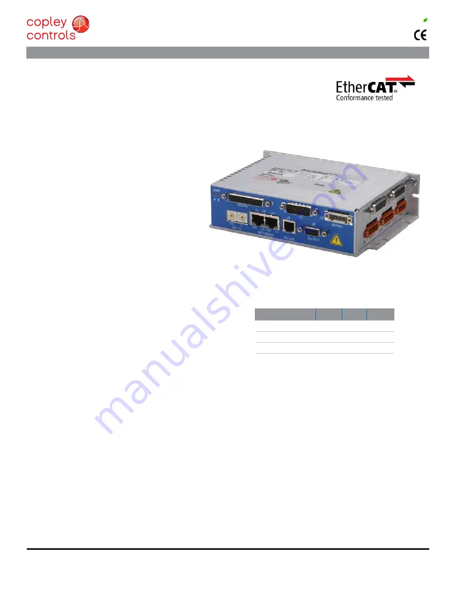
Model
Ip
Ic
Vdc
BE2-090-06
6
3
90
BE2-090-14
14
7
90
BE2-090-20
20
10
90
RoHS
Copley Controls, 20 Dan Road, Canton, MA 02021, USA
Tel: 781-828-8090
Fax: 781-828-6547
Web: www.copleycontrols.com
Page 1 of 33
BE2
Accelnet
Plus
2-Axis
Panel EtherCAT
Current ratings are for each axis
Add -R for resolver feedback option
dIgItal serVo drIVe for brush & brushless Motors
ConTRol MoDES
• Cyclic Synchronous Position-Velocity-Torque (CSP, CSV, CST)
• Profile Position-Velocity-Torque, Interpolated Position, Homing
• Camming, Gearing
• Indexer
Command InTerfaCe
• Canopen application protocol over etherCaT (Coe)
• aSCII and discrete I/o
• Stepper commands
• ±10V position/velocity/torque
• PWm velocity/torque command
• master encoder (Gearing/Camming)
CommunICaTIonS
• etherCaT
• rS-232
FEEDBACk
Incremental Encoders
• digital quad a/B
analog Sin/Cos
Panasonic Incremental a format
• aux. quad a/B encoder / encoder out
Absolute Encoders
• SSI, endat, absolute a,
Tamagawa & Panasonic Absolute A
Sanyo denki absolute a, BiSS (B & C)
Other
• digital Halls
I/o dIGITal
• 8 High-speed inputs
• 2 motor over-temp inputs
• 8 opto-Isolated inputs
• 5 opto-Isolated outputs
• 2 opto-Isolated brake outputs
analoG
• 2 reference Inputs, 12-bit
Safe Torque off (STo)
• SIl 3, Category 3, Pl d
dImenSIonS: In [mm]
• 6.78 x 4.70 x 1.74 [172.1 x 119.3 x 44.1] no heatsink
• 6.78 x 4.70 x 3.14 [172.1 x 119.3 x 79.8] with heatsink
deSCrIPTIon
The BEl models are high-performance, DC powered drives for
position, velocity, and torque control of brushless and brush motors
via etherCaT, an ethernet-based fieldbus. These drives operate
as EtherCAT slaves using the CAnopen application protocol over
etherCaT (Coe) protocol of dSP-402 for motion control devices.
Supported modes include: Cyclic Synchronous Position-Velocity-
Torque, Profile Position-Velocity-Torque, Interpolated Position mode
(PVT), and Homing.
Feedback from both incremental and absolute encoders is
supported. A multi-mode encoder port functions as an input or
output depending on the drive’s basic setup.
There are ten non-isolated inputs and eight isolated inputs.
All inputs have programmable active levels. Five opto-isolated
outputs [ouT1~5] have indi/- connections. Two isolated
moSfeT brake outputs [ouT6~7] are programmable for other
functions and have flyback diodes to the Brake 24V input for driving
inductive loads.
Drive power is transformer-isolated DC from regulated or
unregulated power supplies. an auxHV input is provided for
“keep-alive” operation permitting the drive power stage to be
completely powered down without losing position information, or
communications with the control system.


