background image

15

Chapter 3

Chapter 3

QUICK GUIDE TO ICONS ON THE MAIN SCREEN

This chapter explains the quick access icons on the main screen. Some of
these icon functions will be explained in depth later in the manual. The Main
Screen is the central hub of your Digital Video Recorder. If you scroll your
mouse over any of the icons, a note will appear explaining what that icon
does. Entering the DVR Main Screen, the icons on the right side may be
used to control different functions of your DVR. The following brief descrip-
tion explains how to activate these different functions.

Figure 3-1: The Main Screen

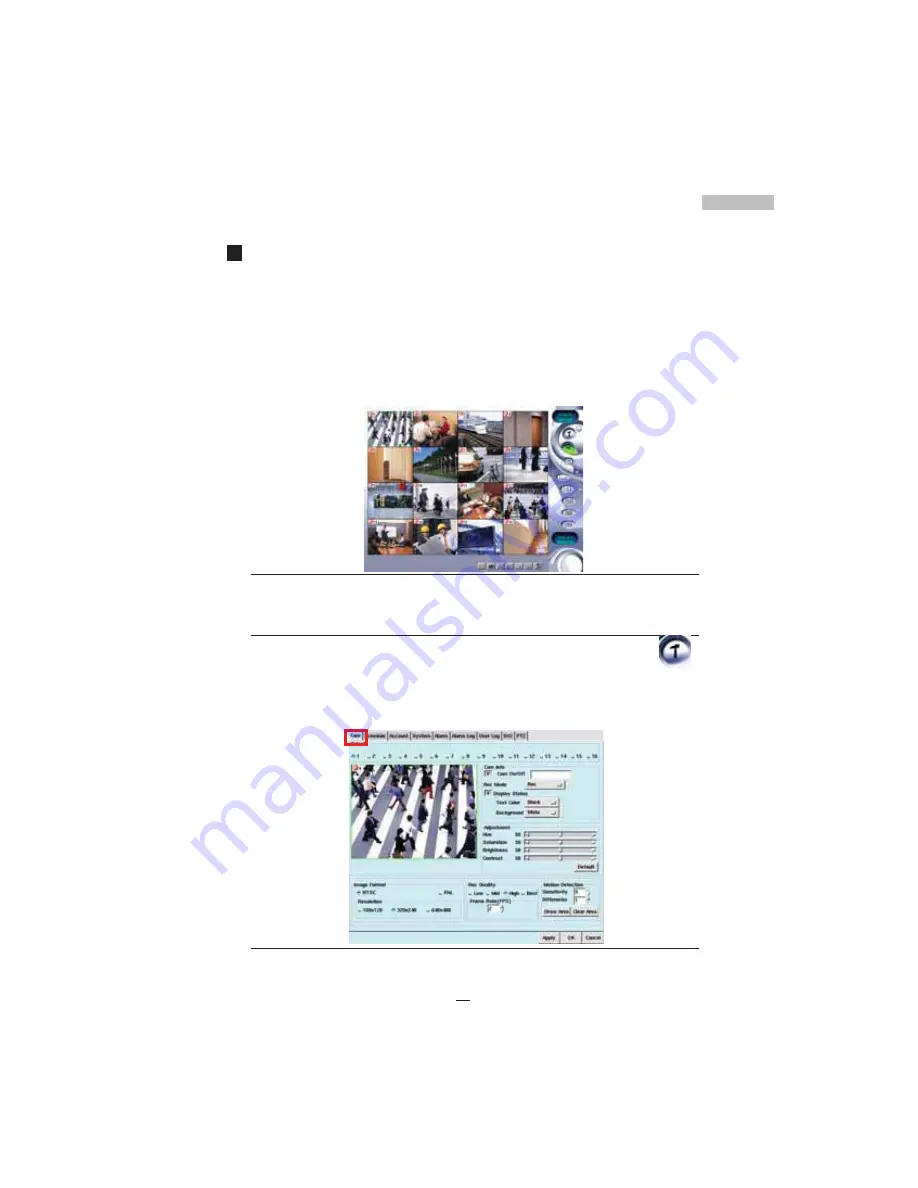
Settings Panel

1. Step 1  Click the 

Setup

 Icon on the right-side toolbar----------- 

2. Step 2  To view the respective configuration windows 

[Cam,

Schedule, Account, System, Alarm, Alarm Log, User Log
and PTZ]

, click on the corresponding tabs.

Figure 3-2: The Settings Main Screen

Содержание Digital Video Recorder

Страница 1: ......

Страница 2: ...Chapter 6 Account Settings 27 Chapter 7 System Settings 31 Chapter 8 Alarm Settings 43 Chapter 9 Alarm Log 51 Chapter10 User Log 55 Chapter11 Configuring General Purpose I O 57 Chapter12 Pan Tilt Zoom 61 Chapter13 Playback 67 Chapter14 Remote Surveillance 81 AppendixA Backup to NAS 111 Appendix B NTP 113 Appendix C Audio 115 AppendixD Multi Playback 119 Appendix E Troubleshooting 121 Appendix F Co...

Страница 3: ...rections will be made as necessary in subse quent editions for the benefit of our customers No guarantee or other hints in any form about the content or usage of this manual is expressed Also the information contained in this document is subject to change without notice Edition 3 5 4 2005 JUN Copyright This publication contains information that is protected by copyright No part of it may be reprod...

Страница 4: ...der in a dusty or dirty work area and the dust in the filter net under the cover should be cleaned at regular intervals 5 Clean your Digital Video Recorder exterior casing regularly with a soft cloth If you use a cleanser make sure that it is only mild detergent and not a solvent Make sure that the Digital Video Recorder s power is off when you clean it After cleaning allow 30 minutes drying time ...

Страница 5: ... 11 Do not use the Digital Video Recorder near water or other liquids or in rainy moist situations If liquid gets into your Digital Video Recorder turn it off and take it to your dealer for inspection 12 Wait for a period of one minute before restarting your Digital Video Recorder after turning it off in order to avoid damage to the hard disk iii ...

Страница 6: ...d The high performance processor and quick I O connection not only provide you with the capability to monitor the camera in real time mode but also utilize the extra processing power to allow for a high frame rate for recording and remote monitoring via I E browser so that there will be a minimal loss of video frames Users can determine the actual frame rate required for recording and remote monit...

Страница 7: ...12 CH 16 CH model at the front of the Digital Video Recorder you will find a cover protecting the hard disk drive cage and connectors Make sure that the cover is in a closed position when the DVR is not in use The cover has a lock in the middle so please follow these steps to open or to close the cover 1 Turn the knob of the lock anti clockwise and the cover can be opened 2 When the cover is in th...

Страница 8: ... computing functions and orchestrating the actions of the system Upgradeable System Memory Memory can be upgraded to 256MB Power Management The DVR features sophisticated power management built into the complete BIOS Setup program Integrated Smart Charger Circuit which is designed to restart the DVR automatically as soon as the power is resumed after a power cut FDD Module The DVR comes with a bui...

Страница 9: ...eo Recorder Front View Figure 1 1 Front View of the DVR Front Inside View Please refer to Figure 1 2 and the following descriptions to identify the components on the front side of the Digital Video Recorder Figure 1 2 Front Inside View of the Digital Video Recorder 4 or 8 Channel Type 12 or16 Channel Type 4 or 8 Channel Type 12 or 16 Channel Type ...

Страница 10: ... Digital Video Recorder comes with a built in 3 5 inch loppy Disk Drive DD 5 Floppy Disk Drive Eject Button Press this button to eject the floppy disk in the DD 6 Floppy Disk Drive LED When the L D is green it indicates that the power is on and when the L D is red it indicates that the loppy Disk Drive is in use 7 Power Button Press the power button to turn the Digital Video Recorder on Press the ...

Страница 11: ...6 Rear View Please refer to Figure 1 3 and the following descriptions to identify the components on the rear side of the Digital Video Recorder Figure 1 3 Rear View of Digital Video Recorder ...

Страница 12: ...card 2 etc since there are 4 available channels per card slot Figure 1 4 BNC pigtail adaptor 4 Ethernet LAN Port se an R 45 LA cable to connect to a LA or Internet 5 VGA Display Port This port is used to connect an external CRT or T T display 6 Printer Port This port is used to connect a printer to the DVR 7 PS 2 Keyboard Port This port connects a PS 2 compatible keyboard 8 PS 2 Mouse Port This po...

Страница 13: ...arm sound 15 Microphone This is used for sound input Preparing the Digital Video Recorder for Operation To prepare your Digital Video Recorder for operation you should first con nect all peripheral devices Make sure the DVR is turned off before you do this Once you have connected all peripheral devices check that the volt age switch is appropriate for your region 115 230 Make sure the floppy drive...

Страница 14: ...Connect the R 45 LA Cable to the thernet LA Card 4 Connect the eyboard and the Mouse to their respective PS 2 Ports 5 Connect the Printer to the Printer Port C M1 is used to connect a M D M with the 4 or 8 channel type a PT camera may be connected to C M1 instead of a M D M and C M2 which is only available for 12 or 16 channel types is used to connect a PT camera 6 Check the Voltage Switch so that...

Страница 15: ...ance Figure 2 2 The first viewable screen Main Screen The first viewable screen not only gives the user a first glance at the GUI Graphical User Interface but also shows all of the connected cameras The viewable screen takes up 75 of the screen while the controls are posi tioned to the right of the viewable cameras Status Lights The lights on the top left corner show the status of recording operat...

Страница 16: ...e Settings Menu 3 Playback Icon Click this icon to enter the Playback Menu 4 Log on Icon Click this icon to enter the Log on Shut down Menu 5 Single View Icon Click this icon to run in Single view mode 6 Quad View Icon Understanding the DVR Main Screen When starting the Digital Video Recorder for the first time please make sure that you understand all of the DVR s icons before moving on Here is an...

Страница 17: ...ic recording it will display Recycle Here is an explanation of the relevant icons on the botton toolbar Bottom Toolbar Figure 2 4 Bottom Toolbar 1 Exit Icon Click this icon to exit the Main Screen 2 Detection Frame Drawing Icon Clicking this icon will allow users to draw a specified motion detection frame in the viewing camera area At most 6 detection regions may be drawn If any object is found mo...

Страница 18: ...creen Enable Disable the auto login please read Chapter 7 System Settings Adding DVR users please read Chapter 6 Account Settings Meanwhile please shutdown the DVR as following Re login When starting the Digital Video Recorder for the first time the system can only provide admin authority for the Supervisor with no other rights for the remaining users So initially you will have to log on with the ...

Страница 19: ... then it can be chose to Login or Shut down Figure2 6 Shut down the system 4 nter or choose admin in the ser name field enter the password or the default password admin 5 Click the Shut down to shutdown the system Figure 2 7 Shutting down the system After logout the DVR system the software version of the DVR system will be shown on the top right of the screen for example ...

Страница 20: ...te will appear explaining what that icon does Entering the DVR Main Screen the icons on the right side may be used to control different functions of your DVR The following brief descrip tion explains how to activate these different functions Figure 3 1 The Main Screen Settings Panel 1 Step 1 Click the Setup Icon on the right side toolbar 2 Step 2 To view the respective configuration windows Cam Sc...

Страница 21: ...Clicking separate windows will display different settings screens The first window is the camera screen Please refer to the instructions later on in this manual Playback Panel 1 Step 1 Click the Playback Icon on the right side toolbar 2 Step 2 View the video database under the Playback Screen Click on a selected file and open the recorded data The red circle indicates the playback image Figure 3 3...

Страница 22: ...meras this view can be configured to display four different camera viewpoints at 6 second intervals 9 Camera View Screen 1 Step 1 Click the 9 Camera View Icon on the right side toolbar 2 Step 2 The screen will display nine camera images in one screen If your DVR system has 16 cameras this view can be configured to display nine different camera viewpoints at 6 second intervals Figure 3 5 The Nine C...

Страница 23: ...ep 2 The screen will display all or the selected cameras connected to the DVR in ull Screen Mode If the system has 16 cameras sixteen camera images will occupy the entire screen 3 Step 3 Click the right key of the mouse to resume original status Figure 3 6 The Full Screen Camera View Screen ...

Страница 24: ...djust the sensitivity of motion detection Please follow these steps to change the settings of each camera 1 Click the Setup Icon on the Main Screen to enter the camera settings screen 2 Click the Diamond Icon to choose the camera you want to configure 3 The small window under the camera selection will then display the selected camera in real time mode Figure 4 1 Main Camera Settings Window Naming ...

Страница 25: ...ckground Color Click the Display Status checkbox to change the text color and background color Text colors or Text Color users can choose to have text in lack Red reen lue and White ackground color or ackground Color users can choose to have lack Red reen lue and White Adjusting Picture Quality nder Adjustment users can choose various settings respectively for i Hue This is the attribute of colors...

Страница 26: ...Setting Image Format nder Image Format users can select i NTSC Three settings for image resolution 160x120 320x240 or 640x480 ii PAL Three settings for image resolution 176x144 352x288 or 704x576 Figure 4 4 Image Format Area Setting Recording Quality Under Recording Quality there are four choices Low Medium High and Best Among them Low quality is applicable for long time recording while Best quali...

Страница 27: ...started Up to six different Motion Detection Windows can be created in one camera view Click Draw Area if you want to draw a motion detec tion frame on the camera images just drag a frame sized window over the desired motion detection area Continue to do this until all the needed frames have been drawn up to 6 detection frames Click Stop After you have clicked drawing area Draw Area will revert to...

Страница 28: ...in all Once Daily Weekly and Monthly Recording under different modes will affect the overall capacity of the hard disk of your DVR Schedule your recording according to your requirements Once the DVR is in recording mode various scheduling times should be set for each different video camera Follow these instructions to configure scheduling 1 Click the Setup Icon on the Main Screen 2 Click the Sched...

Страница 29: ...recording option for ours and Minutes every day Figure 5 3 Record Mode Selection Bar Daily iii Weekly Provides a recording option for users to set the day Sun through Sat and time for recording every week Figure 5 4 Weekly Schedule Settings iv Monthly Provides a recording option that allows users to set the date and time for recording every month Figure 5 5 Monthly Schedule Settings ...

Страница 30: ...orrections The screen will return to viewer mode Once Scheduling By choosing the Once scheduling mode of the DVR users can first select the Day Month and Year and then select a particular time on that date to record The advantage of this operation is to set different times for each individual camera allowing users to record with different cameras at various times This function can be used for PTZ ...

Страница 31: ...uration Figure 5 7 Duration Selection 4 Click the Add button The settings for Weekly and Monthly are the same as above Deleting Schedule Settings Deleting recorded data will permanently delete all related information from the hard disk drive thus freeing up disk space 1 Select the recorded scheduled period from the list Figure 5 8 Deleting Schedule Settings 2 Click the Delete button To Delete All ...

Страница 32: ...to create or configure users for the DVR system 1 Click the Setup Icon on the Main Screen 2 Click the Account Tab Figure 6 1 Account Tab Window 3 nter the name of the user followed by a specified password 4 nter the password once again in the ReType field to reconfirm 5 Click the checkbox next to Enable to select the user s type and authority 6 Select Supervisor to give a user total control over t...

Страница 33: ...w config from remote to enable users to change their system configuration through a browser over the LA or Internet 12 Click Allow Playback to enable users to playback the recording files 13 Click Allow Control PTZ to enable users to control PT cameras 14 Select a checkbox to mark a given camera as available to the user being created or modified This function is primarily utili ed to restrict a gi...

Страница 34: ...ettings 1 Select the user 2 Make the changes in the Main Account Panel 3 Click the Modify button 4 Click Apply then OK to confirm changes To Delete Users 1 Select the user 2 Click delete 3 Click Apply then OK to confirm the changes ...

Страница 35: ...30 NOTES ...

Страница 36: ...d time consuming Follow these steps to set up your DVR machine s 1 Click the Setup Icon on the Main Screen 2 Click the System Tab Figure 7 1 System Tab Note NAS NTP and Audio are optional please read the Appendix to understand the operating steps 3 Type in a name for the DVR host up to 32 letters for the purpose of machine identification when sending an email alarm 4 Enter the Host s IP Address Su...

Страница 37: ...been assigned 1 Check the ADSL dial up and enter the account and password of ADSL Figure 7 2 System Tab 2 Click the Dialup button IP address will be shown in this column when connecting succeeded ou can click Dial n oot 3 When connection succeeded click Dynamic D S to show the DD S setting window as below and enter the account and password Please enter a easy to memory account Figure 7 3 DDNS sett...

Страница 38: ...Register ser register account and IP by himself Right contrary to Auto register after connection 5 Save Save the settings nly after saving would enable all your settings Modem Dial up DVR users can choose modem dial up for connecting external Network Windows users can also dialup using PPP to DVR for remote monitoring To set up modem diap up do the following Check the Dialup in the Internet field ...

Страница 39: ...e printed images may reveal more detail than can be seen clearly on the monitor The system supports a variety of printers your DVR Supplier will provide related information To set up a printer do the following 1 click printer setup 2 and then the window shows a list of system support printer types Figure 7 5 Printer Types ...

Страница 40: ...em can back up the system configuration files to an external device which will greatly aid the rebuilding of the system in the future should that become necessary These backup system configuration files may also be recopied to allow quick setup of multi DVR systems The system supports a variety of user selectable back up devices 1 click Backup Config 2 then the screen will list the back up device ...

Страница 41: ...he screen will show a list of user selectable back up devices Figure 7 8 Restore Device Selection 3 select the device you want 4 then click OK Setting the System Clock The System Clock is automatically adjusted according to the system BIOS If the system time is incorrect then it may be necessary to change the system clock and time zone After the changes are made click Apply and then OK Figure 7 9 ...

Страница 42: ...he System Tab 2 nder Others click the checkbox next to Recycle Rec Figure 7 10 Recycle Rec Option 3 Click Apply then OK to activate the changes Auto Login A second option is to give the administrator and other users Auto Login status when the system is started Users with this status do not have to enter a username and password every time they log in 1 Click the System Tab 2 nder Others click the c...

Страница 43: ...ok to activate the operation Minimize Video Size Minimizing the video size allows the DVR System to save more hard disk space but the system performance will likely be somewhat degraded due to additional processing requirements associated with the video compres sion algorithms 1 click the system tab 2 under the Others item click Minimize Video Size 3 click Apply then OK to activate the setting Num...

Страница 44: ...disk 3 the speed of data transmission When the P frame function is set to a value higher than the default setting for every clip of video less I Frames are sent so the quality of the image will be normal but transmission occurs more quickly and disk space is saved on the contrary when the P Frame function is set to a value lower than the default setting more I frames are sent and the quality of th...

Страница 45: ...ew HD format Support file system including ext3 more stable the default setting or vfat When using vfat format the HD can be mounted to Windows system for playback 1 click the System tab 2 under the Others item select the suitable file system for your new D 3 Click Apply then OK to apply the change Virtual Server Setting If the DVR is only provided with one legal IP and besides the DVR host there ...

Страница 46: ...the three ports assigned by Virtual Server Example etwork nvironment please consult the et Supervisor of your company xterior legal IP 211 23 141 2 Interior etwork of the company 192 168 1 Interior etmask of the company 255 255 255 0 Default Router IP of the company 193 168 1 1 Interior D S Server 192 168 1 2 DVR ost Setting Mode Virtual IP 192 168 1 3 IP 192 168 1 3 etmask 255 255 255 D S Server ...

Страница 47: ...42 Figure 7 14 Reboot ...

Страница 48: ...tand alarm settings Motion Detection on each camera can be configured under the first setting screen Cam However users may not be aware when motion detection is triggered Under Alarms periods of time can be set up so as to trigger an alarm when motion is sensed There are four areas of configuration Camera Pre alarm recording Enable Trigger Period and Alarm Trigger ing Device 1 Click the Alarm Tab ...

Страница 49: ...is camera and DI 6 Then select one of the Triggering Devices from the Tab field windows below Alarm Record Triggering The following shows how to use Record Alarm 1 Click the Alarm Tab first 2 rom the General tab select the Duration for motion detection triggering and click the checkbox next to AdjustFrameRateTo to select the frame speed for the motion detection Figure 8 2 General Field 3 Select th...

Страница 50: ...irst 2 Select the Camera Din Disk full Disk failure or No signal 3 Select Enable or Enable Trigger Period 4 Click the Sound Tab Figure 8 3 Sound Tab 5 Click the Select button to choose alarm sound from the sound list window Figure 8 4 Sound Selection Window 6 Choose a wav file from the above window and click OK 7 Click Play to play the file 8 Select how many times you would like to repeat the alar...

Страница 51: ...the Camera Din Disk full Disk failure or No Signal 3 Select a Trigger Period 4 Click the Message Tab Figure 8 5 Message Tab 5 Then click Add the window below will show Message 6 Click Apply and OK Once this function is enabled and users have enabled Motion Detection on that particular camera a pop up screen will appear as below to warn users that the DVR has detected motion Figure 8 6 Message Pop ...

Страница 52: ...A total of 14 bytes may be used 4 Delay seconds means how many seconds you d like to delay before the Alarm Voice is activated A period of 1 to 10 seconds may be set see picture below 5 Repeat Times is used to set the number of times you d like to trigger the alarm 1 to 10 times can be set see picture below Figure 8 7 Voice Tab 6 Then click Add the drop down window will show Voice with the selecti...

Страница 53: ...e below Figure 8 8 Fax Tab 6 Then click Add and the window below will show Fax with the selections made 7 Click Apply and OK Alarm Email Triggering Alarm email may email a warning message at the time of detecting an alarm condition Follow the instructions below to set up Alarm email 1 Click the Alarm Tab 2 Select the Camera Din Disk full Disk failure or no signal 3 Specify the desired Trigger Peri...

Страница 54: ...deo may be played by the email recipient s If the recipients have already downloaded the playback program file you do not need to choose this option again 8 Then click Add and the window below will show EMAIL with the selections made 9 Click Apply and OK Alarm Digital Output Triggering Alarm Digital Output may activate the digital output at the time of detecting alarm Follow the instructions to se...

Страница 55: ...Then click Add and the window below will show Dout with the selections made 10 Click Apply and OK Figure 8 12 Output Port settings The user could also modify an alarm that has already been set after chang ing the content please click Modify to confirm you could also move the cursor up and down to adjust the sequence of alarm responses or click Del to eliminate unnecessary alarm responses Tick off ...

Страница 56: ...nd of alarm the time the alarm was triggered and the description of the alarm triggering event Thus you can handle the entire alarm status conveniently The log is simple and allows the administrator only two options a to delete a single log b to delete all log files Follow the next few steps to set this up Deleting One Log 1 Click the Alarm Log Tab 2 Select the file you wish to delete Figure 9 1 A...

Страница 57: ...ick Apply then OK to complete the task Deleting All Logs 1 Click the Alarm Log Tab 2 Click Del all 3 A confirmation pop up screen will appear asking you to reconfirm Figure 9 3 Confirmation Window 4 Click Confirm to continue or Cancel to reset 5 Click Apply then OK to complete the task ...

Страница 58: ...addresses were This is only a user log the information cannot be changed Information in this log can only be deleted or else the entire log file can be deleted Follow these few steps to delete files Deleting One Log 1 Click the User Log Tab 2 Select the file you wish to delete Figure 10 1 User Log Selection File 3 Click the Del button 4 A confirmation pop up screen will appear asking you to reconf...

Страница 59: ...Deleting All Logs 1 Click the User Log Tab 2 Click Del all 3 A confirmation pop up screen will appear asking you to reconfirm Figure 10 3 Confirmation Window 4 Click Confirm to continue or Cancel to reset 5 Click Apply then OK to complete the task ...

Страница 60: ...iple sets of alarm equipment through the inde pendent alarm signal line The 4 channel type DVR may have four DI DO the 8 channel type may have eight DI DO the 12 channel type may have eight DI DO and the 16 channel type may have 16 DI DO The related DO relay output and sensor input are configured as follows Figure 11 1 Rear View of DVR with GPIO interface ...

Страница 61: ...h a voltage of less than 5V Depending on their attributes the sensors can be set to Normal Open NO or Normal Closed NC according to the users application requirements Normal open NO When the sensor is of the NO type DI is connected to the NO connec tion of the sensor and GND is connected to the COM connection of the sensor When the alarm is triggered the circuit connected to the alarm sensor input...

Страница 62: ...al Closed value for each DI accord ing to the type of connected sensor using the following screen and also select the appropriate Delay time the DVR system alarm delay interval for each connected sensor Figure 11 4 DIO Setting Output Settings DO relay output could support connected alarm equipment rated as high as 0 5A 24V DC and also could be configured for either normal open or normal closed out...

Страница 63: ... If the DO relay output is set to be normally closed when an alarm is triggered The DO relay output of the DVR will transition from closed to open The user can specify the connection point number and also select a closed or open condition under the Manual Dout Control in order to test the functionality of any given connected alarm device Figure 11 6 Manual Dout Control setting ...

Страница 64: ...5 2 Vido Protocol CD 55 3 Pelco Protocol Pelco D and Pelco P Pelco Spectra III series 4 SA Protocol CD 55 CD 56 CD 65 5 PA AS IC Protocol only support for WV CS850 WV CS854 Traditional Protocol 6 Dynacolor Protocol D7722 D77 7 MD icecam MP1000 MD1800 8 atatel 312 Protocol The user should contact their dealer for information regarding which PTZ cameras they can provide at present This chapter shows...

Страница 65: ...fer from the number shown on the screen should this occur please set the camera number to be the same as the PTZ ID to enable the user to control the PTZ camera Note For specific details of device setup information please refer to the PTZ product documentation Note If the PTZ device Baud rate setting does not match the corresponding Baud rate setting of the DVR then the device will most likely not...

Страница 66: ...ltant changes to the screen output Once you understand how to control the PTZ device then you could start to learn the following additional PTZ device functionality Focus When connecting a PTZ camera to your Digital Video Recorder you have the option to focus in on the picture Use to focus in to focus out and to have the camera automatically adjusted Iris When connecting a PTZ camera to your Digit...

Страница 67: ...set point field this ranges from 0 degree per second to 255 degrees per second and the duration Time range from 0 to 255 seconds to make adjustments to preset speed and duration time for the PT camera 4 nce complete click the Save button 5 To view any of the preset camera pictures in later time just insert the appropriate camera number in the Preset field 6 Click Clear one preset to delete a prese...

Страница 68: ...gin to Auto Pan according to the presets in the group Figure 12 6 Pan Group Example Setting Group 1 Choose roup 1 and click Set Group button Function To operate presets 1 to 4 automatically in the mode of Run Sequence Setting Group 1 and Group 2 Choose roup 1 and roup 2 and click Set Group button Function To operate presets 1 to 8 in the mode of Run Sequence Setting Group 1 Group 2 and Group 3 Cho...

Страница 69: ... T START 3 SET END this parameter is used to set the current preset point as the S T D 4 SCAN SPEED used to select the speed from 0 255 for PT camera A T PA After finishing the selection of this setting please click SET SPEED to save the setting Figure 12 7 Pan Scan The DVR system supports many PTZ camera types which have different functions and a variety of settings so please read the related cam...

Страница 70: ...this chapter Let s first take a look at how we can review playback To view Playback click the Playback Icon A pop up database window will appear giving you the choice of selecting a file Selecting by Date Time and Camera or by checking the list of all files you are able to choose record files At the bottom of the screen you will notice a set of icons These icons will help later when using the play...

Страница 71: ... to choose all cameras 5 Reset click reset to clear the current data and reset the new files you choose 6 Other path click other path to choose the recording files under other path 7 Back up choose the file you need to back up and click Backup to back up files NOTE Press Shift and mouse s left button at the same time you can choose multipe files 8 Search Button Click the Search button to list all ...

Страница 72: ...icon to turn the mute on or off Click the directional icons to move the playback images up down left or right Click this icon to remove blur to sharpen or define the image Click this icon to blur the image Click this image to take a snapshot one selected frame form the current video file and export or print the snapshot image Click this image to save an image to disk Click this icon to tag an impo...

Страница 73: ... next file If the current file has been only partially played then you can click on this icon once to jump to the end of this file press it a second time to jump to the beginning of the next file on the same camera if the current file has reached the end press this icon to jump directly to the beginning of the next file on the same camera Viewing Playback by Camera To view a recorded file from a p...

Страница 74: ...st the desired files or click List to show all the files 5 Then the recorded database will be listed on the screen if the camera is defined with a name the name will appear in the Description field Figure 13 6 Recording Database 6 Choose the recorded file to play Figure 13 7 Camera Selection ...

Страница 75: ...from the selected file will appear in the top left hand corner of the Main Screen Figure 13 8 Recorded Data Playback 8 Click Play from the ottom Toolbar 9 Double click the image to enlarge Figure 13 9 Enlarged Image 10 Double click the image again to enlarge ...

Страница 76: ...layback Follow these steps to view alarm triggered playback images 1 Click the Alarm Icon 2 A database of all the alarm triggered playback files will appear Alarm Log Figure 13 11 Alarm Log 3 Please select the file you want from the alarm video log Double click it or click Open The selected file will appear in front of the Main Screen ...

Страница 77: ...ion can be tagged for later reference While watching the video frames the tagged section can be operated like this 1 Click the Tag button to enter the window Figure 13 13 Tag Field 2 Type in the Tag name first 3 Click the Insert button the information about the Camera Tag time and Description the camera name will be added to the system automatically and then be listed out ...

Страница 78: ... the camera number and the time is in sync with the tag data 5 Then a mark will appear at the left bottom of the tagged screen see the image below Figure 13 15 Tagged Image Exporting an Image While viewing playback data if you wish to export a section of a file to save in addition do the following 1 Click this icon and the following window will appear ...

Страница 79: ...son of the two methods of Video Export Note1 The installation program for playback program is DvrActiveXSetup exe which would be allocated on the same directory of exported data files When users click on the DvrActiveXSetup exe installation will be initiated automatically and will run playback right away Note2 If your PC already installed the playback program you can click directly on the exported...

Страница 80: ...hen click NEXT to continue 4 The DVR then asks you to choose the media and the destination for the file to and the name of the file nce complete click OK to confirm If the space is not big enough for the export file the system will inform you beforehand and stop the export mode Figure 13 17 Export Image 2 Smoothing an Image The smoothness and sharpness of an image can be adjusted in the DVR When a...

Страница 81: ...se it to blur the image when the Sharpen Icon appears you can use it to sharpen the image Figure 13 19 Blur Image Moving playback frames While viewing several playback screens the entire screen or background screen may be shut out The directional icons can be used to move each playback video to different parts of the screen Click on the separate direc tions to position your video to the desired lo...

Страница 82: ...pshot icon to pop up a new window to show the image Figure 13 21 Snapshot 2 Click the bottom tool bar export icon to save the image individually The system will let you choose the ways to export and the place to save and also the file name After keying in the information please click OK to confirm ...

Страница 83: ...tion 3 Click the print icon to print out the image individually If you print it out successfully the screen will pop up a new window to show you please click Confirm to indicate that the files have printed out Figure 13 23 Print OK Window ...

Страница 84: ...y from the System Window you are able to easily and conveniently operate your Digital Video Recorder remotely 1 Click the Setup icon from the Main Screen of the DVR system 2 Click the System Tab Figure 14 1 System Tab Screen for LAN Identification 3 Identify your IP address 4 pen your browser 5 In the address field enter the IP address 6 it Enter The DVR remote logon window will appear 7 nder ame ...

Страница 85: ...logon Window 10 The next screen is the Main Remote Surveillance Screen No motion over 10 minutes after login users will be auto logout Figure 14 3 The Main Remote Surveillance Screen enter the name enter the password click login ...

Страница 86: ...Click this area to close all operations and return to the login screen Let s go over the following sections one by one in detail Monitoring 1 Click the Monitor button When you use the DVR system for the first time a warning window will appear outlining the problems of using Active X For more information please refer to Appendix F Figure 14 4 ActiveX Warning Once you have clicked the Monitor button...

Страница 87: ...eo This screen also displays the name of the current user 2 Click Select All to view monitoring screens from all cameras in the new window Four degrees of image quality may be selected Low Mid High Best Figure 14 6 Image Quality Field 3 Click first the left button Clear All 4 Then Check the camera you want to view to show logining user s name Monitor image quality selection Save the selected camer...

Страница 88: ...s Real Time Monitor Window The Real Time Monitor Window is the key window of remote monitoring user can monitor selected cameras The user can also click the left mouse button twice to enlarge the selected camera window and click the right mouse button to restore the enlarge camera window The Maximum FPS of each camera will be shown on the upper left side of the real time monitoring screen Figure 1...

Страница 89: ...Click or to adjust the Max speed 0 30 FPS as below Figure 14 8 Adjust maximum display speed Click icon to export images to HDD or print it out via printer as below Figure 14 9 Focused camera image export 1 ...

Страница 90: ...isplaying bandwidth click it to display the bandwidth click again to hide the information Figure 14 11 show the bandwidth The second icon on the upper right side of the real time monitor window may be used to minimize the window Figure 14 12 Minimize real time monitor window ...

Страница 91: ...ng information Also displayed are the following user PTZ control functions Now two tab settings will be visible on the upper right side of the window 1 Recording time is displayed 2 If recycling recording is taking place then a green recycling recording icon is also displayed 3 the amount of space which has been used on each hard disk and the space remaining for up to a total of 7 hard disks 4 A h...

Страница 92: ... a green recycling recording icon is also displayed 3 the amount of space which has been used on each hard disk and the space remaining for up to a total of 7 hard disks 4 A hard disk damage icon is displayed if there is damage to a hard disk 1 An indication whether each camera has an alarm event for motion detection a green light shows normal status a red light is alarm mode 2 An indication wheth...

Страница 93: ...o go to the next frame 6 File Button Click this button to choose the file you want to view 7 Alarm File Button Click this button to find an alarm recorded file 8 Tag File Button Click this button to find a file by its tag 9 Snapshot Button Click this button to take a snapshot and print it out 10 Export Button Click it to export and save an image to output devices 11 Tag Button Click this button to...

Страница 94: ... There is a horizontal scroll bar on the bottom of the playing window which facilitates users in searching films quickly You may press and hold the left mouse button on it and drag it from left to right until you find the video image that you need Playback by File You may click Playback to view the files remotely 1 nce you have clicked the File icon 2 A new pop up window will appear allowing you t...

Страница 95: ...o click the List button to list all the recorded files Figure 14 16 Information on File Selection 5 Move the mouse to the file you want to play and double click the file to play it r you can click it and press the Open button below to play the file 6 When you want to see an enlarged image just click on the operation options to enlarge it ...

Страница 96: ...m File Alarm File allows users to see the time and camera numbers concerned with an alarm and all the alarm files can be deleted 1 Click Alarm 2 Select one alarm file click Open to play it 3 Click the Delete button to delete one alarm file Figure 14 18 Alarm File ...

Страница 97: ...ion options 320x240 480x360 and 640x480 Figure 14 19 Snapshot Resolution 640x480 3 Choose the Resolution and click Print ou will be prompted to select a printer from a pop up window 4 Select your printer and click Print to print Exporting an Image Exporting an image allows users to access images remotely from the hard disk and save it onto your local hard drive 1 Click the Export button 2 Select a...

Страница 98: ...ntly Inserting a Tag Inserting a tag allows users to mark an important section of a file specially Once it s opened the tagged file will be played from the marked place After adding the tagged files click the Tag in the file options a pop up window will list all the tagged files The following tells how to produce a tagged file 1 Click the Tagadd button 2 After entering the Tag ame click the OK but...

Страница 99: ...ss Tag Figure 14 22 Tag Window NAS Click this button you can playback the video clips that back up in NAS Configuring Setup Remotely The functions for remote setup are basically the same as those used locally The following instructions outline this in detail 1 n the Main Remote Screen click Setup 2 The next screen is the Camera setup window ...

Страница 100: ...vided in Appendix F All remote functionality is set up similarly to the local machine The major difference is the way the interface looks On the left side of the viewing area are the function keys for setup Clicking any of the keys will lead you into the related setup screen Then you can choose the camera and set related parameters on the right side of the viewing area Figure 14 24 Remote Camera C...

Страница 101: ...e lack Red reen lue and White NOTE It will change the text and background color of DVR site not your browser site 5 Background Color the optional colors are lack Red reen lue and White 6 Recording Mode there are 3 modes o Recording Recording and Schedule 7 Hue Saturation Brightness Contrast sers can adjust the value or click to choose the default value 50 50 50 50 8 Motion Detection Frame Setting ...

Страница 102: ... and RI T icons to move the cameras 11 Zoom In button Zoom Out button 12 Iris nlarge Iris button Reduce Iris button 13 Focus earer ocus button urther ocus button 14 Auto Pan check this to make the PT cameras circumgyrate automatically 15 Video Image Quality there are 4 options Low Mid igh and est 16 Image Resolution users may choose from 160x120 320x240 and 640x480 17 Image Format TSC or PAL forma...

Страница 103: ...n to reset Remote Schedule Configuring Click the Schedule link to view the Remote Schedule Set tings Figure 14 27 Remote Scheduling Window The remote schedule screen is divided into various parts for easy configuration Select the Rec Mode and Camera to start the configuration 1 Click the Date Icon and a pop up calendar window will appear for you to select ear Month and Day ...

Страница 104: ...dule Window 3 nce complete click Add to activate the settings After you have completed all schedule settings you can view a log of all changes at the bottom of the window Modifying Scheduled Settings 1 Click the data you wish to modify 2 Click the Modify button after having changed the scheduled settings ...

Страница 105: ...the Account Settings screen as the Administrator you can see the authority settings of all the users Of course you are able to Add Delete a user and to modify a user s setting And all your modifications will be saved to the local Host 1 Click the Account link on the browser to enter the main remote account screen Figure 14 30 Normal Account Settings Screen 2 Click Add to add a user 3 Set the users...

Страница 106: ...e accessible cameras Remote user can give the rights for changing password remote setup furthermore As a normal user your access authority is limited in some aspects When you log on a window will appear as below Figure 14 32 Normal Account Screen Click Monitor to show the camera s images that been speci fied during setup time Figure 14 33 Normal Account Logon Screen ...

Страница 107: ...102 If no authority is granted at the time of account setup then you cannot change the password Figure 14 34 Normal User Change Password Window Remote System Setup Figure 14 35 Remote System Settings ...

Страница 108: ...e version number Version 3 5 4 will be visible in the header 3 Internet In this field you can setup the info regarding to Internet and modem dial up a DNS Server IP b Default Gateway IP c The corresponding Virtual Server TCP ports 4 Current System Time the System Time Date to be changed 5 Limot out bandwidth ew D format nable telnetd Minimi e video si e and the number P frames after I frames 6 Rec...

Страница 109: ...orner to save the changes to the Host and make them effective Remote Alarm Log Viewing Here all the detailed logs about the alarms will be listed out including the cause triggered time and the descriptions of the triggering condition Through the use of the logs you will be able to view the status of all of the alarms conveniently And to delete an unnecessary alarm log check the log on the right si...

Страница 110: ... 14 38 Delete Alarm Log Remotely Remote User Log All the users having entered the system will be recorded with the data notes of their entering and leaving the system The log shows where the users entered from and their logon logoff time thus the Administrator is able to see the current status of the system Click the Login Log link to view the user log remotely Figure 14 39 Remote User Log ...

Страница 111: ...GPIO is the same as with local settings on the DVR host Once you have added all the GPIO modes click Submit in the right corner to save the changes to the Host and make them effective Figure 14 40 Remote GPIO Setting Window After completing all the settings or after using this function click Main to use other remote functions Or you can click Logout to leave the remote monitoring system ...

Страница 112: ...here Traditional DAS Direct Attached System cannot meet these requirements anymore Steps 1 Click the Setup icon on the main screen 2 Click the System tab 3 Click the NAS button to popup the asSetup windows Figure A 1 Click NAS button 4 Enable Click the Enable checkbox to enable the AS feature 5 Path ill in the backup pathname including the IP ost name of AS and the DVR backup folder name on AS ex ...

Страница 113: ...er or equal to the Lowerbound This procedure will be continued till the free space is more or equal to the Upperbound 9 Backup Period DVR will not keep archiving data to AS the ackup Period is the time interval to make sure AS synchroni ed with the DVR and backup new data to AS In default the system will auto backup data every 1 minutes 10 Volume Volume is the total available space for your DVR ba...

Страница 114: ...rotocol NTP is used to synchronize the clock of DVR to another reference time source in the network Steps 1 Click the Setup icon on the main screen 2 Click the System tab 3 Click the NTP button to popup the TP setup windows Figure B 1 Click NTP to synchronize the clock of DVR Appendix B ...

Страница 115: ... TP server 6 Deactive ot to active the selected TP server 7 Delete Delete the selected TP server in the list 8 Sync Period Click the Hourly Daily Weekly or Monthly you can have DVR be timed every hour day week or month ote DVR will only connect with the top one acted TP server within the list but if the connection failed DVR will connect the second one and so on 9 Time Adjust manually correct the ...

Страница 116: ...ording Providing audio recording and audio playback via built in audio device of mothboard Steps 1 Click the Setting icon on the main screen 2 Select System Settings 3 Click the Audio button to pop up the setting window Figure C 1 Click the sound button Appendix C ...

Страница 117: ...select no recording it will no sound when playback 3 uality select igh or Low The better quality the bigger file si e is needed Playback Property Click Mute for mute mode or adjust the volume slider for volume control Note The volume is irrelative with the file s capacity 1 The real time monitoring and playback screen with audio Click the audio icon to switch to mute mode ...

Страница 118: ... Appendix C Figure C 3 Real time monitoring screen with audio Figure C 4 Playblack screen with audio 2 The real time monitoring and playback screen in mute mode Click the mote icon to switch to audio mode ...

Страница 119: ...114 Figure C 5 Real time monitoring screen in mute mode Figure C 6 Playback screen in mute mode ...

Страница 120: ...nction 1 Click the playback button on the main screen and then click multi playback you ll see the Multi Playback windows as below Figure D 1 Multi playback screen 2 Click to select the playback clips according to cameras and date time Figure D 2 Playback setting for the date time and camera Appendix D ...

Страница 121: ...lti playback respectively 4 Click OK and then click the icon to playback 5 ou can use our and Minute to change the start playback time x Click the hour the playback time will be changed from 14 00 to 15 00 6 ou can click any camera view to oom out its image Figure D 3 Zoom out the image of camera ...

Страница 122: ... plugged in and securely connected If you are using a power strip or surge protector ensure that these devices are turned on Improperly connected cables cause often problems If you are using periph erals such as a mouse or keyboard make sure they are properly connected to their respective ports Ensure that none of the connectors pins are bent or broken Check all cables connected to the Digital Vid...

Страница 123: ...e power ou may also need to check the fuses and breakers in your electric box If the outlet is controlled by a wall switch make sure that the switch is on If your Digital Video Recorder is plugged into a power strip with an n ff switch make sure the switch is on With the Digital Video Recorder s power switched off check all cable connections If the Digital Video Recorder is connected to any periph...

Страница 124: ... status These non critical malfunctions are those that cause incorrect results that may not be readily apparent An example of a non critical error would be a memory chip failure In general if the POST detects a system board failure a critical error the Digital Video Recorder halts and sends out a series of beeps If failure is detected in an area other than the system board such as the display key ...

Страница 125: ...120 NOTES ...

Страница 126: ...e relative settings of ActiveX can be configured in the manner described below When you get into the system the window will pop up a warning screen which is about the Active X setting the details are as follows Figure F 1 Warning Window The user could check Always trust content from Softwell Technology Co Ltd and then click yes to continue Figure F 2 Install DVR ActiveX ...

Страница 127: ...installer you want to install 1 DVR ActiveX to copy the file to the computer 2 Start Menu Shortcuts Figure F 3 Objects Selection Figure F 4 Install Location Selection Figure F 5 Installation Window After finishing installation then click Close ...

Страница 128: ...9 34 src rpm PL 13 cpio 2 4 2 20 src rpm PL 14 gawk 3 0 6 1 src rpm PL 15 initscripts 5 83 1 src rpm PL 16 net tools 1 57 6 src rpm PL 17 ed 0 2 19 src rpm PL 18 grep 2 4 2 5 src rpm PL 19 gettext 0 10 35 31 src rpm PL 20 tar 1 13 19 4 src rpm PL 21 g ip 1 3 12 src rpm PL 22 procps 2 0 7 8 src rpm PL 23 setserial 2 17 2 src rpm PL 24 mount 2 10r 5 src rpm PL 25 sh 3 0 8 8 src rpm PL 26 gnome libs ...

Страница 129: ...tic 59 V lib2 2 25 1 12 src rpm PL2 60 samba client 2 0 7 36 src rpm PL2 61 logrotate 3 5 4 1 src rpm L PL 62 chkconfig 1 2 22 1 src rpm L PL 63 glibc common 2 2 2 10 src rpm L PL 64 audiofile 0 1 11 1 src rpm L PL 65 gtk 1 2 9 4 src rpm L PL 66 gdk pixbuf 0 8 0 7 src rpm L PL 67 glib 1 2 9 1 src rpm L PL 68 ree86 devel 4 0 3 5 src rpm ree86 69 cgic201 tar g cgic Please refer to http www perl com ...

Страница 130: ......

Отзывы: