Cooper Tools Cleco mPro400GC Скачать руководство пользователя страница 6

Page 6

PL12-1004EN

03/31/2010

Cleco

®

mPro400

GC

Controller

1.3

Mounting the Controller

1. Loosen the two long mounting screws at the bottom of the controller so the mounting plate can be

separated from the controller, see Figure 1-17.

2. Figure 1-16 illustrates the bolt pattern for hanging the mounting plate on a wall. Note the hole-size

dimensions so the correct size bolts are chosen. Size ¼” or M12 bolts (4) should fit the mounting

plate holes and support the controller.

3. Once the mounting plate is installed in its location the controller can be hung on the bracket

utilizing the four studs protruding from the back of the controller. Once in place, the controller can
be secured at the bottom using the two long screws removed in Step 1.

1.4

Making Connections to the Controller

1. Connect the cable to the tool.
2. Connect the other end of the cable to the controller. The connector at the controller is an Air-LB

connector and utilizes a push-pull style connector. Before attempting to attach the cable verify that

the collar on the controller connector is pushed towards the controller. If the collar is pulled away

from the controller the cable will not connect to the controller. Insert the cable connector and pull

the collar away from the controller (towards the cable) to lock the cable in place.

3. Insert the power cord into the controller and into a 115 or 230 VAC power source.
4. Using the ON/OFF power switch at the front of the controller power the controller ON.
5. Refer to the Programming Manual, PL12-1001EN, for all other connections.

1.5

Accepting a Corded Tool

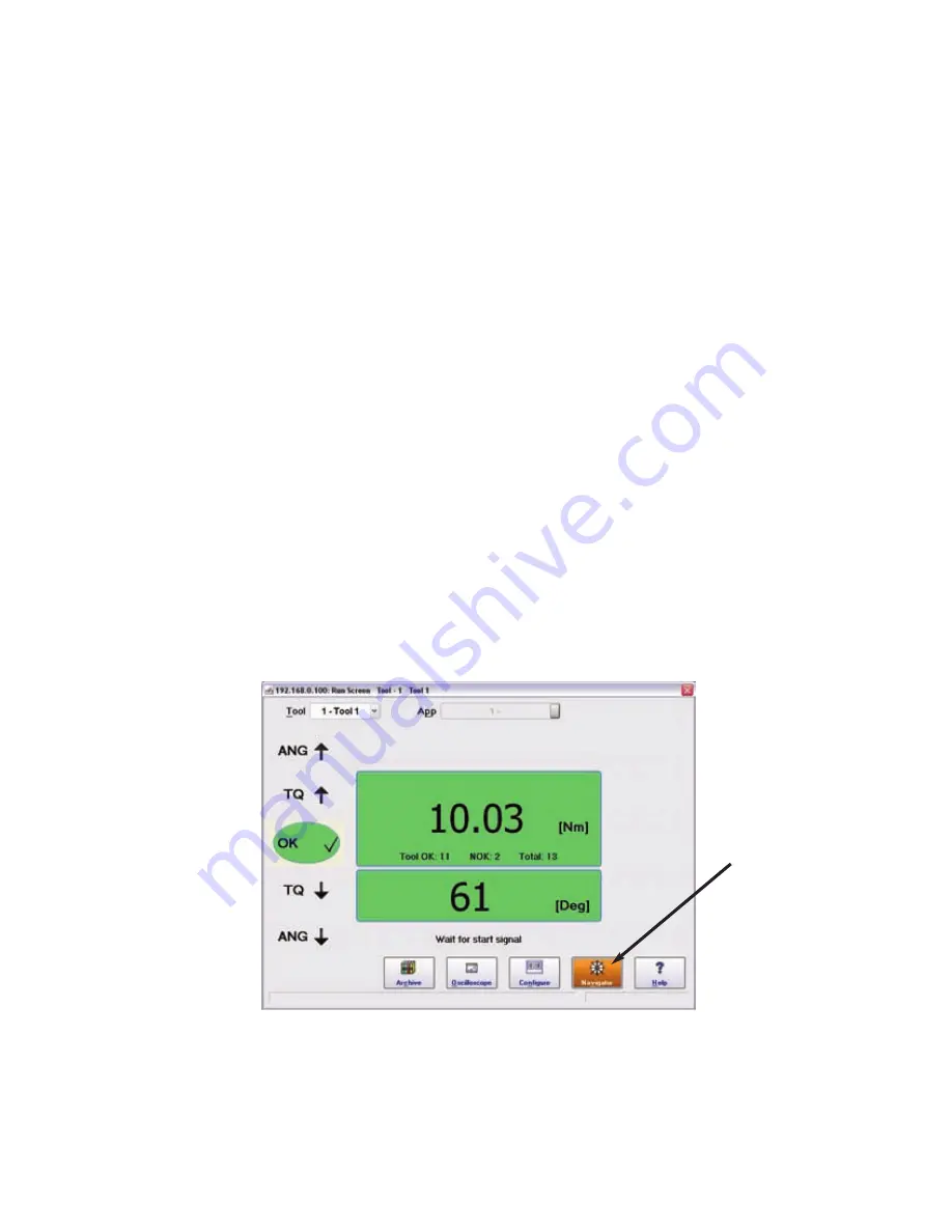
1. When the controller has finished booting up it should advance to the RUN screen. The screen is

a touch screen. At the lower right corner of the screen press the Navigator button as shown in

Figure 1-2.

Figure 1-2: Run Screen

Navigator Button

Содержание Cleco mPro400GC

Страница 1: ...Quick Set Up Guide PL12 1004EN 03 31 2010 mPro400GC Global Controller For additional product information visit our website at http www cooperpowertools com...

Страница 2: ......

Страница 3: ...safety instructions in this quick set up guide all local safety and accident prevention rules must be observed This warning sign identifies all references to potential electrical shock alerting of haz...

Страница 4: ...Page 4 PL12 1004EN 03 31 2010 Cleco mPro400GC Controller...

Страница 5: ...ver any information presented in this section To avoid the hazard of electrical shock or burn the following instructions must be adhered to Failure to follow these instructions may also cause damage t...

Страница 6: ...tool 2 Connect the other end of the cable to the controller The connector at the controller is an Air LB connector and utilizes a push pull style connector Before attempting to attach the cable verify...

Страница 7: ...roller 2 From the Navigator menu press TOOL SETUP 3 Touch the horizontal bar indicating the Primary tool to highlight it Touch the Tool Settings button Figure 1 3 Navigator Screen Tool Setup Figure 1...

Страница 8: ...n the window that appears press the ACCEPT button for that window A screen will appear indicating that the settings are being saved When the save process is complete press the CANCEL button to return...

Страница 9: ...cable Plug the cable into the X1 Ethernet port see Figure 1 17 2 Apply power to the controller and access point Setting Up the Livewire Tool Controller IP address 1 From the NAVIGATOR screen press th...

Страница 10: ...serial connectivity has been made the SSID Encryption and remaining fields will become available for programming Enter a value for SSID If Encryption is selected enter a Network Key and confirm it by...

Страница 11: ...ould highlight in orange Position 1 is reserved for the Primary or corded tool 2 Press the Install button and select the Livewire w WLAN choice from the pop up window that appears Enter the IP address...

Страница 12: ...ogramming a Basic Fastening Strategy From the Navigator menu press the BASIC button and the BASIC programming screen with appear Verify that the tool and application are correct Select a fastening str...

Страница 13: ...Go to the Navigator screen and press BASIC From the BASIC screen press the Auto Program button Enter the desired final stage torque value using the virtual keypad Press the Enter key Press the OK butt...

Страница 14: ...row on the keyboard to move the keyboard down so the next field can be entered Continue entering parameters and moving the keyboard If the keyboard won t move any further in a particular direction tou...

Страница 15: ...1 2010 Cleco mPro400GC Controller Figure 1 16 Mounting Information 1 825 46 4mm 0 075 1 9mm 14 88 378mm 4x 1 315 33 4mm 4x 7 750 197mm 10 38 263mm 2x 1 250 31 8mm 2x 12 500 318mm 10x 313 1 95mm 10x 50...

Страница 16: ...X4 X8 X5 X7 X10 Mounting Bracket Screw X11 X9 Mounting Bracket Screw X1 Ethernet Connector 1 X2 Ethernet Connector 2 X3 USB ports 2 X4 Serial Connector 1 X5 Serial Connector 2 X6 I O Connectors X7 Any...

Страница 17: ...troller or an external 24 volt supply such as a PLC The following examples utilize Tool Start as an Input and Cycle OK as an Output Pin I O Signal Description Pin I O Signal Description 12 Out GND2 24...

Страница 18: ...supply in the controller or an external 24 volt supply such as a PLC The following examples utilize Tool Start as an Input and Cycle OK as an Output Pin I O Signal Description Pin I O Signal Descripti...

Страница 19: ...nnected to the external 24 volt supply Pin Function Description Pin Function Signal Description 12 Out GND2 24 Out GND2 11 In Common GND 23 In Common GND 10 Output O 03 22 Output O 07 9 Output O 02 21...

Страница 20: ...4786 Westhausen EMEA Cooper Power Tools GmbH Co OHG Postfach 30 D 73461 Westhausen Germany Phone 49 0 73 63 81 0 Fax 49 0 73 63 81 222 HTWE sales cooperindustries com Coventry UK Cooper Power Tools Gm...

Отзывы: